Magnetic rotary die

a rotary die and magnetic technology, applied in the field of rotary cutting dies, can solve the problems of substantial difference in die positioning cost between screw change method and magnetic die method, and the magnetic die plate to creep out of position, so as to achieve the effect of reducing the positioning cost of the di

Inactive Publication Date: 2005-03-03
PAPER BENDERS SUPPLY
View PDF30 Cites 19 Cited by
  • Summary
  • Abstract
  • Description
  • Claims
  • Application Information

AI Technical Summary

Benefits of technology

[0004] An object of an embodiment of the present invention is to provide a rotary cutting die which is magnetic. By using a magnetic rotary cutting die, screws and clamps need not be used, and the die can be repositioned on the die cylinder by taping lightly on the die plate, moving it in the direction of the desired position adjustment. Occasionally, excessive cutting pressure may cause the magnetic die plate to creep out of position. Therefore, preferably a magnet is positioned on the die cylinder, against the die plate, to prevent creeping. The difference in die positioning cost between the screw change method and the magnetic die method is substantial.

Problems solved by technology

Occasionally, excessive cutting pressure may cause the magnetic die plate to creep out of position.
The difference in die positioning cost between the screw change method and the magnetic die method is substantial.

Method used


Image

  • Magnetic rotary die
  • Magnetic rotary die
  • Magnetic rotary die

Examples


Embodiment Construction

[0013] While the invention may be susceptible to embodiment in different forms, there are shown in the drawings, and herein will be described in detail, specific embodiments of the invention. The present disclosure is to be considered an example of the principles of the invention, and is not intended to limit the invention to that which is illustrated and described herein.

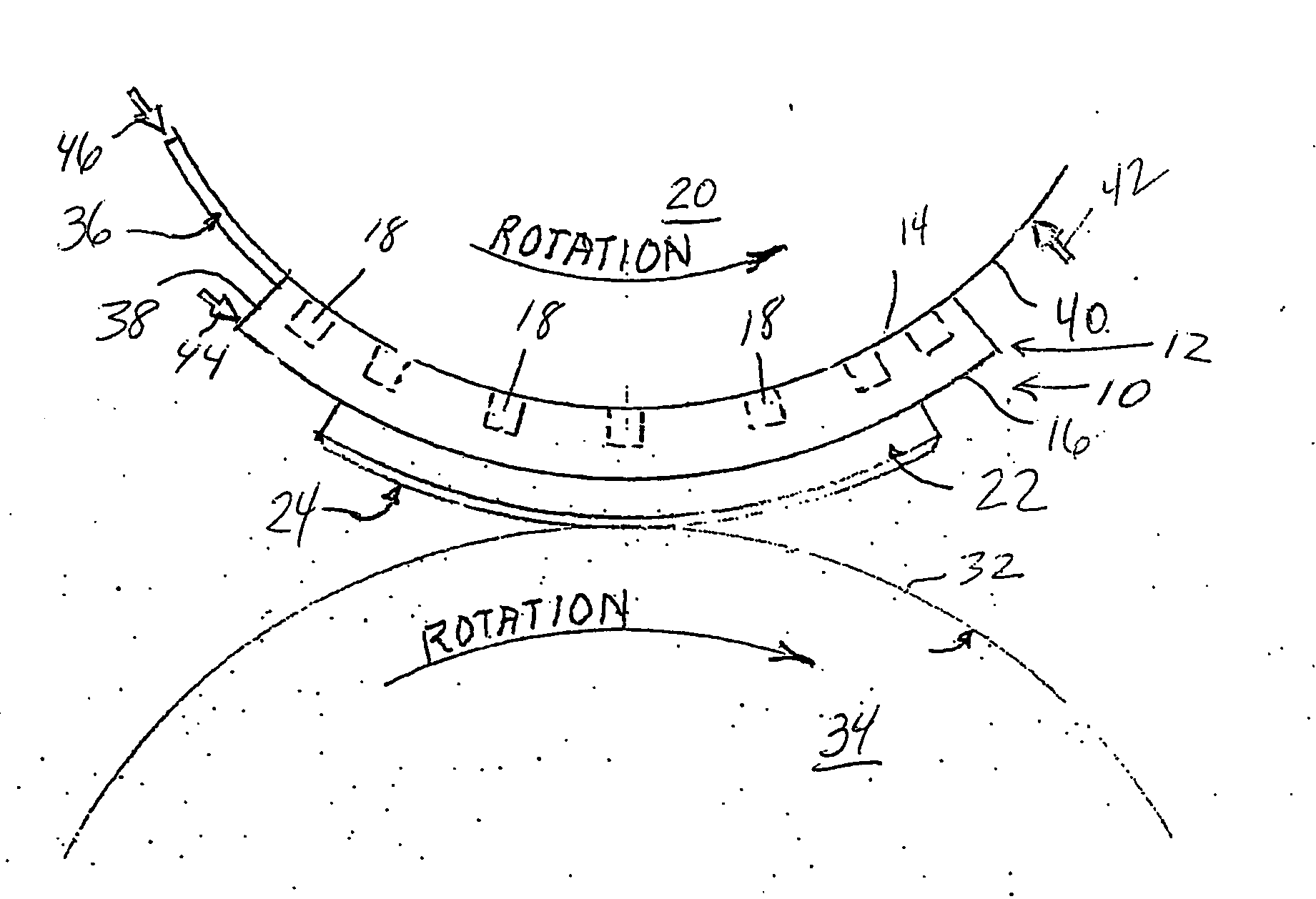
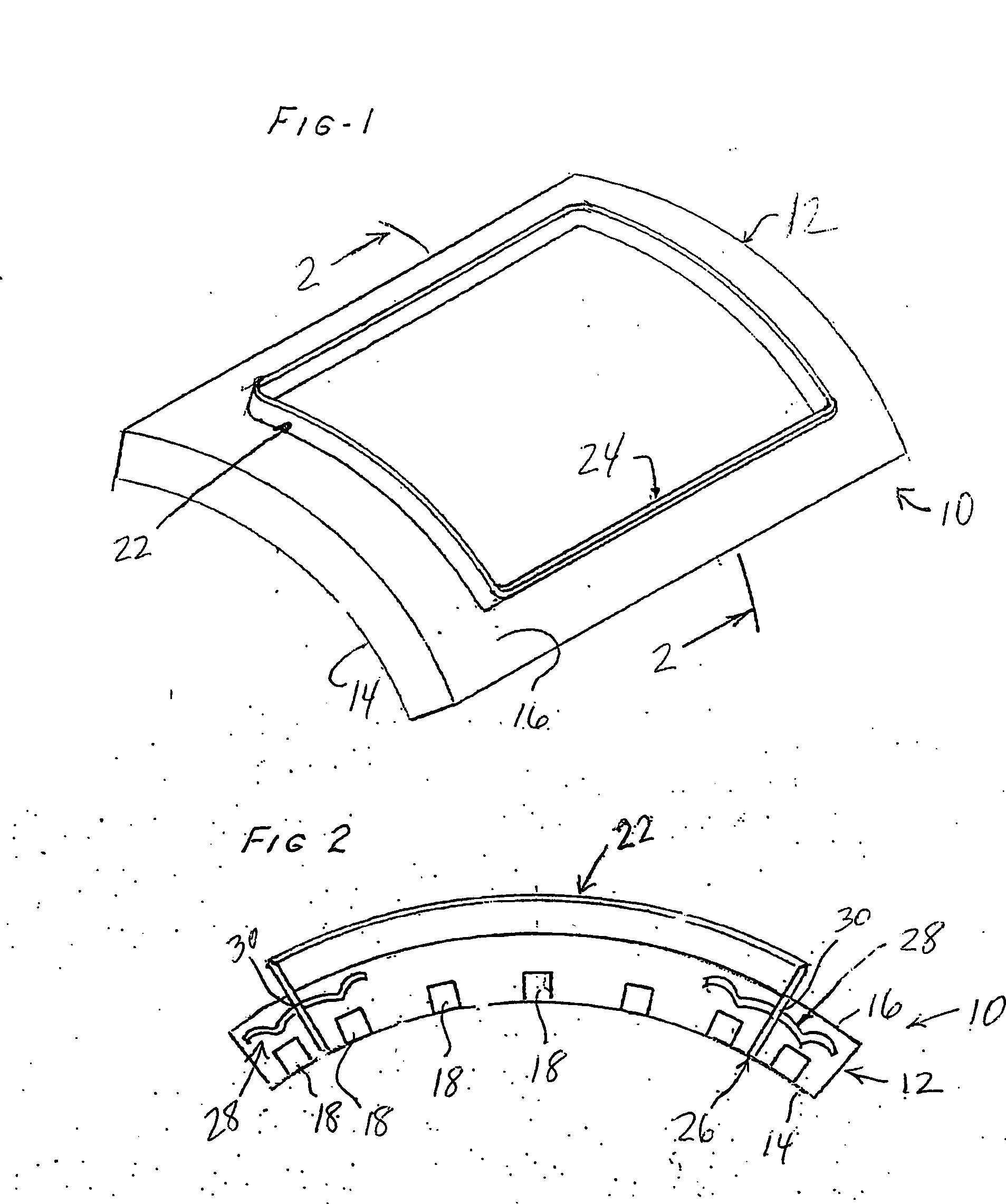
[0014]FIGS. 1 and 2 illustrate a rotary cutting die 10 which is in accordance with an embodiment of the present invention. The rotary cutting die 10 is magnetic in that it is mountable to a metal cylinder via magnetic attraction. By using a magnetic rotary cutting die, screws and clamps need not be used, and the die can be repositioned on the die cylinder by taping it lightly.

[0015] The cutting die 10 includes a rotary die plate 12 which is curved, or arcuate, and includes a concave, inner surface 14 and a convex, outer surface 16. A plurality of magnetic elements 18 are impregnated in the rotary die plate 12, pr...


PUM

PropertyMeasurementUnit
thickaaaaaaaaaa
thickaaaaaaaaaa
thickaaaaaaaaaa

Abstract

A rotary cutting die which is mountable on a metal cylinder. The rotary cutting die includes a rotary die plate having a concave, inner surface which is magnetically attractable and magnetically mountable on a metal cylinder. A cutting blade is mounted on a concave, outer surface of the die plate. Connectors may be engaged with the cutting blade and the die plate. A plurality of magnetic elements, such as neodymium magnets, are in the rotary die plate. The magnetic elements make the inner surface of they die plate magnetically attractable to the metal cylinder, thereby providing that the rotary cutting die is mountable on the metal cylinder without having to use screws, clamps or other mechanical holding devices. To prevent creep of the cutting die during operation, a magnetic member, such as a rubber magnet, may be magnetically mounted on the die cylinder, against the die plate.

Description

RELATED APPLICATION (PRIORITY CLAIM) [0001] This application is a continuation-in-part of U.S. patent application Ser. No. 10 / 654,656, filed Sep. 3, 2003, which is hereby incorporated herein by reference in its entirety.BACKGROUND OF THE INVENTION [0002] The present invention relates generally to the field of rotary cutting dies, and relates more specifically to an improved design for the use of such dies. [0003] Rotary cutting dies have been manufactured and used for numerous years. Rotary cutting dies are disclosed, for example, in the following U.S. Pat. Nos.: 2,993,421; 3,969,474; 4,210,047; 5,379,671; 5,595,093; and 6,067,887, all of which are incorporated herein by reference in their entirety. Conventionally, rotary cutting dies are formed from a resinous die plate material which supports a steel cutting blade. The cutting blade extends above the surface of the resin die plate and defines the cutting shape. The shape created by the steel cutting blade is employed to cut, score...

Claims


Application Information

Patent Timeline
Patent Type & Authority Applications(United States)
IPC IPC(8): B26D7/26B26F1/44
CPCB26D7/2614B26F2001/4463B26F1/44B26D2007/2607Y10T83/04Y10T83/483Y10T83/9459
Inventor HAMILTON, JAMES T.RILEY, RANDY S.
Owner PAPER BENDERS SUPPLY
Why Eureka
Try Eureka