Bill validator with centering device

a centering device and bill validator technology, applied in the field of bill validators, can solve the problems of frequent maintenance and inspection of the centering device, defective prior art bill validating device, etc., and achieve the effect of reducing the number of structural components, reducing the warpage resistance of the centering bill, and simplifying the structur

Active Publication Date: 2005-03-03
JAPAN CASH MASCH CO LTD
View PDF13 Cites 32 Cited by
  • Summary
  • Abstract
  • Description
  • Claims
  • Application Information

AI Technical Summary

Benefits of technology

[0006] The bill validator with a centering device according to the present invention comprises: a conveyer device (8) for inwardly transporting a bill inserted from an inlet (7) into the validator along a passageway (6); a validation sensor (18 to 20) for converting a physical feature of the bill moved along the passageway (6) into electric signals; a control device (60) for receiving the electric signals from the validation sensor (18 to 20) to discriminate authenticity of the bill and drive the conveyer device (8) in response to the result of the authenticity discrimination; a centering device (14) mounted on the validator (1) ahead of the validation sensor (18 to 20). The centering device (14) comprises a pair of pinch jaws (15) positioned on the opposite sides of the passageway (6), and a centering motor (30) for moving the pinch jaws (15) toward and away from each other for reciprocation of the pinch jaws (15) so that the pinch jaws (15) come into contact with side edges of the bill between the pinch jaws (15) to align a central line of the bill with a central line of the passageway (6). As the centering motor (30) stalls when warpage resistance of the centered bill is greater than inherent holding torque of the centering motor (30), the centering device (14) can have the simplified structure with reduced number of structural components for light weight and reliable centering operation. And then, the conveyer device (8) further inwardly transports the bill along the passageway (6).

Problems solved by technology

However, prior art bill validating devices are defective in that the equipped centering device has the very complicated structure with increased number of structural components, and therefore, requires frequent maintenance and inspection of the centering device.

Method used


Image

  • Bill validator with centering device
  • Bill validator with centering device
  • Bill validator with centering device

Examples


Embodiment Construction

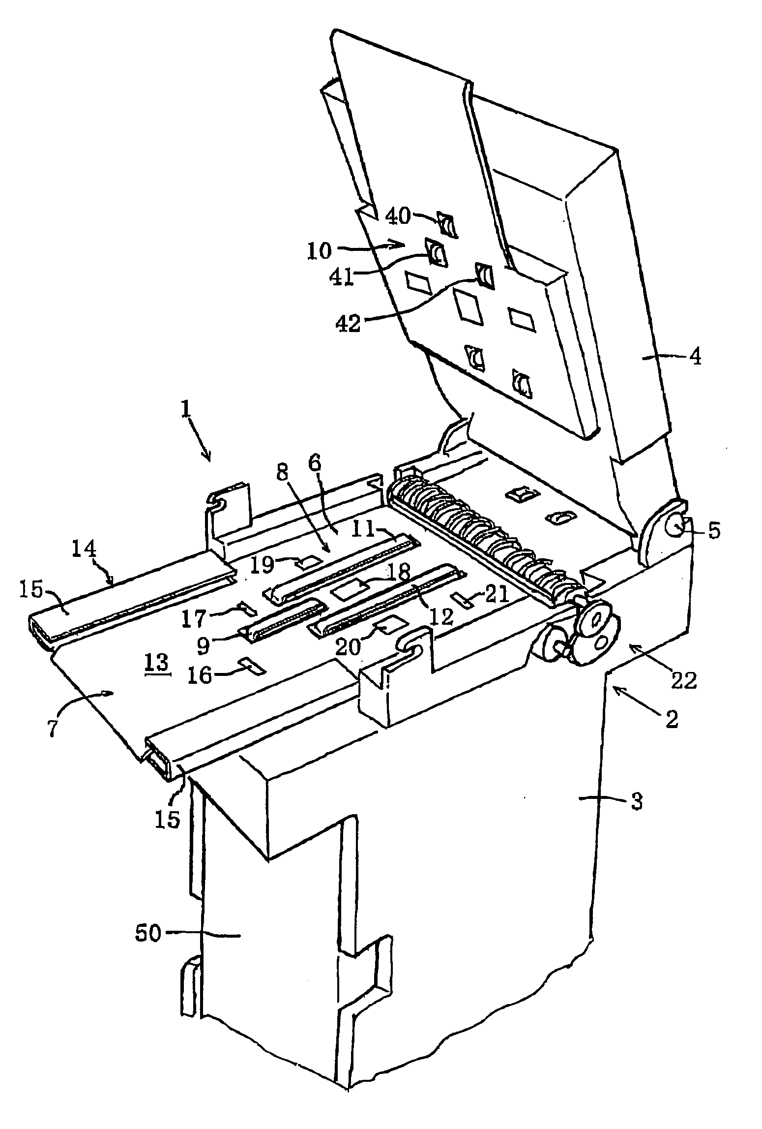
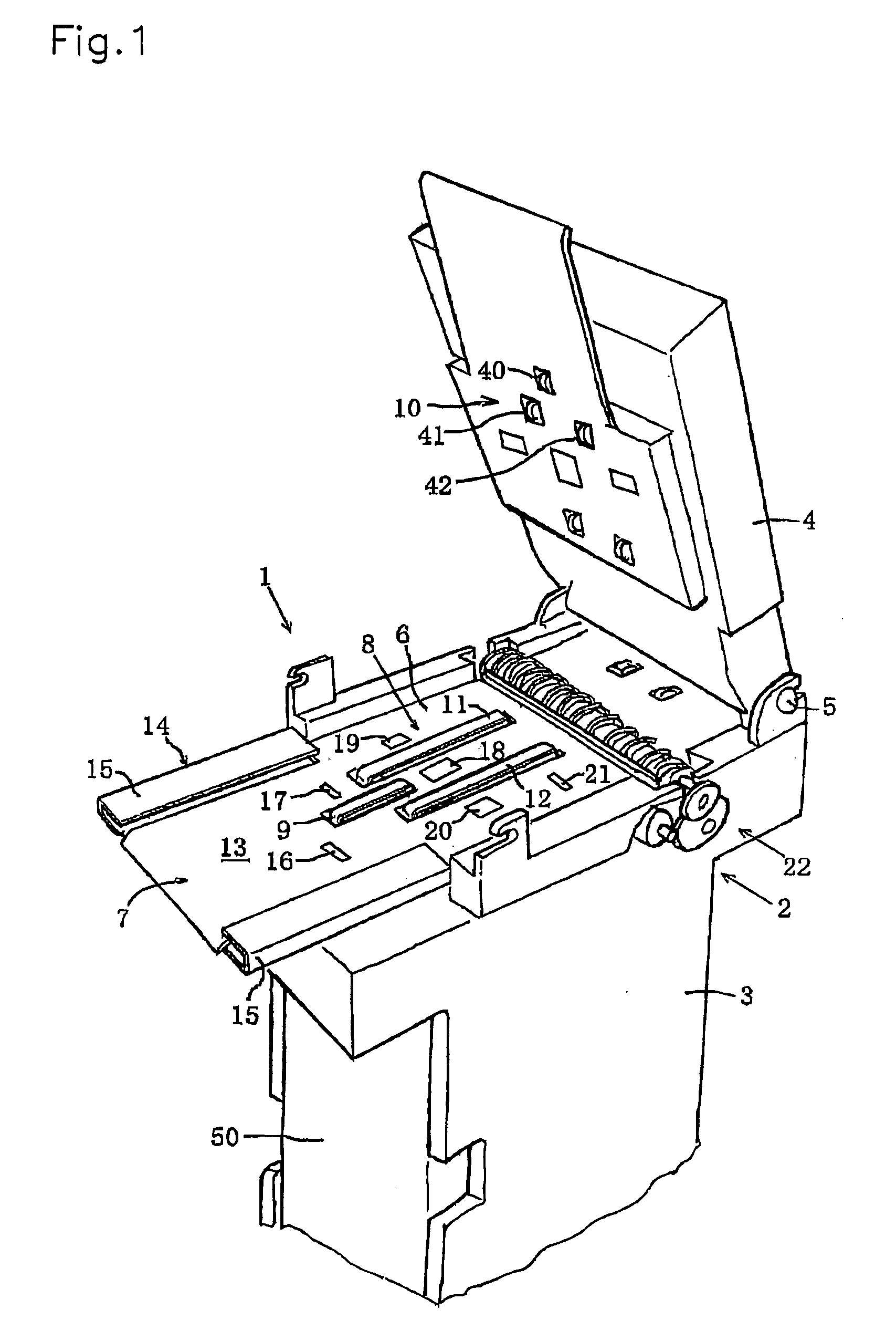
[0022] With reference to FIGS. 1 to 13, an embodiment is described hereinafter of a bill validator with a centering device according to the present invention.

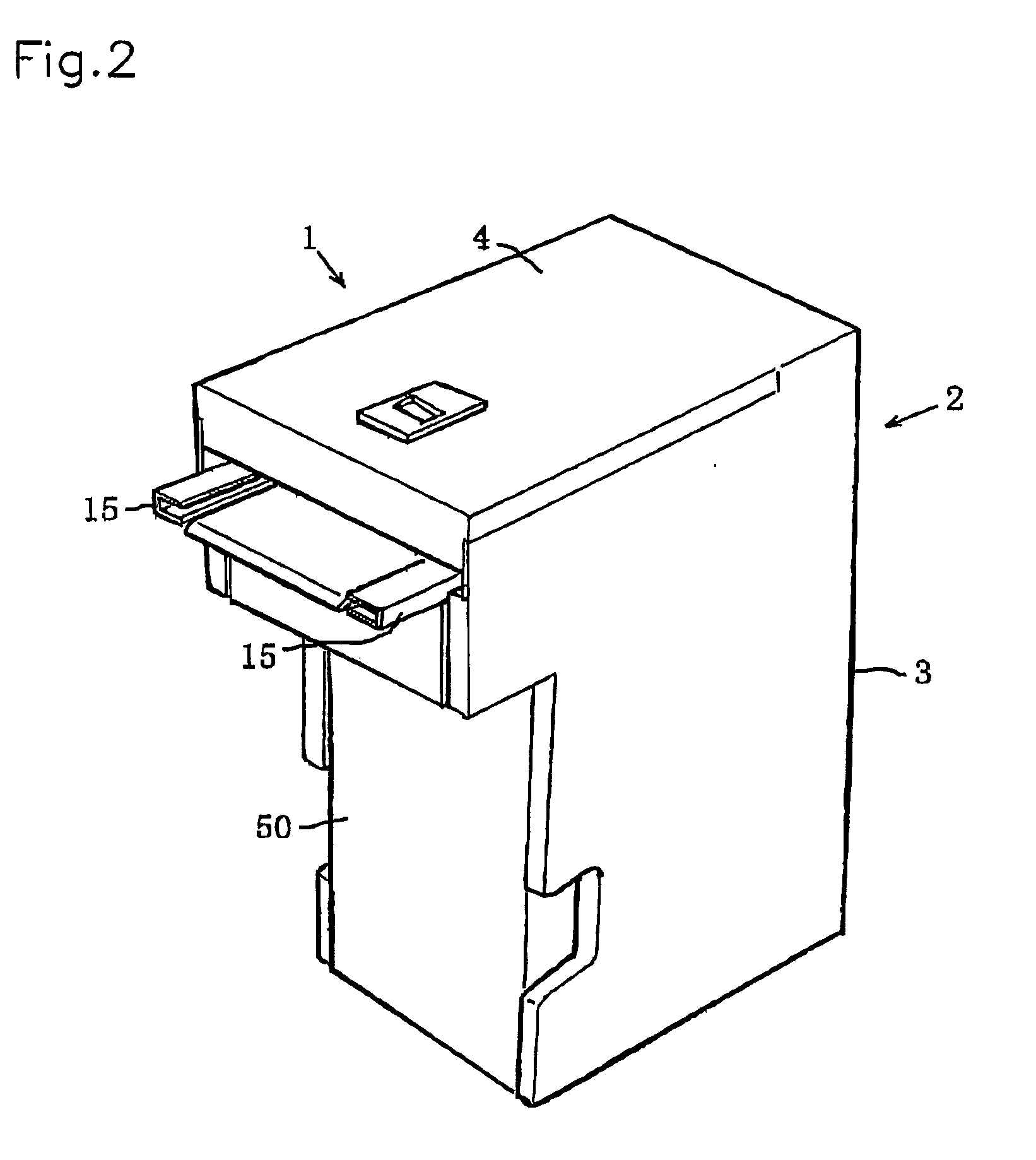
[0023] As shown in FIG. 1, the bill validator 1 of the present invention comprises a casing 2 formed of a metallic material such as aluminum which includes a lower casing 3 and an upper casing 4 rotatably mounted on lower casing 3. Specifically, upper casing 4 is rotatably and removably mounted on lower casing 3 by means of a casing shaft 5 to define a passageway 6 between lower and upper casings 3 and 4. Provided in lower casing 3 is a stacker device 50 which receives and stores bills considered to be genuine and moved along passageway 6.

[0024] An inlet 7 is formed at a front end of passageway 6 to insert a bill into inlet 7, and a conveyer device 8 is attached in the middle of passageway 6. Conveyer device 8 comprises a front belt 9 supported on lower casing 3, a pair of side belts 11, 12 positioned in the opposite sides of...


PUM

PropertyMeasurementUnit
physical featureaaaaaaaaaa
warpage resistanceaaaaaaaaaa
holding torqueaaaaaaaaaa

Abstract

Centering device 14 of a bill validator comprises a pair of pinch jaws 15 positioned on the opposite sides of a passageway 6, and a centering motor 30 for moving pinch jaws 15 toward and away from each other for reciprocation of pinch jaws 15 so that pinch jaws 15 come into contact with side edges of a bill between pinch jaws 15 to align a central line of bill with a central line of passageway 6. As centering motor 30 stalls when warpage resistance by centered bill is greater than inherent holding torque of centering motor 30, centering device 14 has the simplified structure with reduced number of structural components for light weight and reliable centering operation.

Description

FIELD OF THE INVENTION [0001] This invention relates to a bill validator, in particular, of the type which has a centering device capable of centralizing bills of different widths along a longitudinal central axis of a bill passageway in the validator. DESCRIPTION OF THE PRIOR ART [0002] When a banknote or bill is inserted into a bill validator, an inlet sensor detects the inserted bill to produce from the inlet sensor a detection signal used to start to activate a conveyer. Then, the bill is moved by the conveyer through a validation sensor mounted in position along a bill passageway so that the validation sensor scans a predetermined position on bill to detect a physical feature such as optical or magnetic feature of the bill. To stably detect any physical feature from bills, the bill is centralized to register a longitudinal central line of the bill with a central line of the passageway so that the validation sensor can always scan a predetermined position of bills of even differ...

Claims


Application Information

Patent Timeline
Patent Type & Authority Applications(United States)
IPC IPC(8): B65H9/10G06K13/16G07D7/04G07D7/12G07D7/16
CPCB65H9/101B65H2301/36212B65H2701/1912G06K13/16G07D7/04G07D7/168G07D7/12B65H2220/15G07D7/17
Inventor NAGO, TOKIMIOKAMOTO, KAZUHIKOSEKI, TORU
Owner JAPAN CASH MASCH CO LTD
Why Eureka
Try Eureka