
Extracting apparatus

Active Publication Date: 2005-03-03
FUJIFILM HLDG CORP +1
View PDF8 Cites 13 Cited by
  • Summary
  • Abstract
  • Description
  • Claims
  • Application Information

AI Technical Summary

Benefits of technology

[0012] The primary object of the present invention is to provide an extracting apparatus, which is capable of automatically performing quick and efficient extraction of a nucleic acid from a sample liquid and is capable of performing the extraction of the nucleic acid through optimum supply of pressurized air in accordance with the kind of the sample liquid.
[0013] Another object of the present invention is to provide an extracting apparatus, which is capable of being kept small in size, and in which problems with regard to contamination are capable of being prevented from occurring, and extraction accuracy is capable of being kept high.

Problems solved by technology

However, the conventional nucleic acid extracting apparatus described above has the problems in that, in cases where the nucleic acid extracting apparatus has a large size so as to be appropriate for analyses of large amounts of samples and in cases where the number of the samples is small, and the frequency of analyses is low, the cost of the nucleic acid extracting apparatus is not capable of being kept low, and the processing efficiency is not capable of being kept high.
However, the problems described below occur with the nucleic acid extracting apparatus proposed in U.S. Pat. No. 5,645,723.
As a result, the problems often occur in that the processing on sample liquids having a comparatively high viscosity is not capable of being completed.
In cases where the capacity of the reduced pressure is increased in order to prevent the aforesaid problems from occurring, the size of the extracting apparatus is not capable of being kept small.
Also, due to a large volume of the reduced pressure, a long time is required to obtain the reduced pressure.
Further, it is not always possible to detect the completion of the discharging of all of the sample liquids.
Therefore, the setting time is not capable of being kept short, and the processing efficiency is not capable of being enhanced.
Furthermore, the problems occur in that a sample liquid having a low viscosity is vigorously discharged from the filter tube, and a bubble-like splash of the sample liquid clings to an adjacent filter tube and an adjacent area of the rack and causes contamination to occur.
As a result, the accuracy of the analysis is not capable of being kept high.
In particular, with the extracting apparatus, in which the areas within all of the filter tubes are simultaneously subjected to vacuum suction, the problems occur in that, in cases where air resistance does not occur in one of the filter tubes due to a sample liquid injection failure, a filter tube loading failure, or the like, a normal operation is not capable of being performed.
Also, it is not always possible to constitute a mechanism for performing independent sucking operation for each of the plurality of the filter tubes.
However, a specific extracting apparatus is not disclosed.
In the extracting apparatus which adopts the pressurization method, problems will arise in its pressurization control method.
Problems will also arise in contamination due to scattering of the discharged liquid during pressurization, reliability in sealing, or the like.

Method used


Image

  • Extracting apparatus
  • Extracting apparatus
  • Extracting apparatus

Examples


Embodiment Construction

[0062] The present invention will hereinbelow be described in further detail with reference to the accompanying drawings.

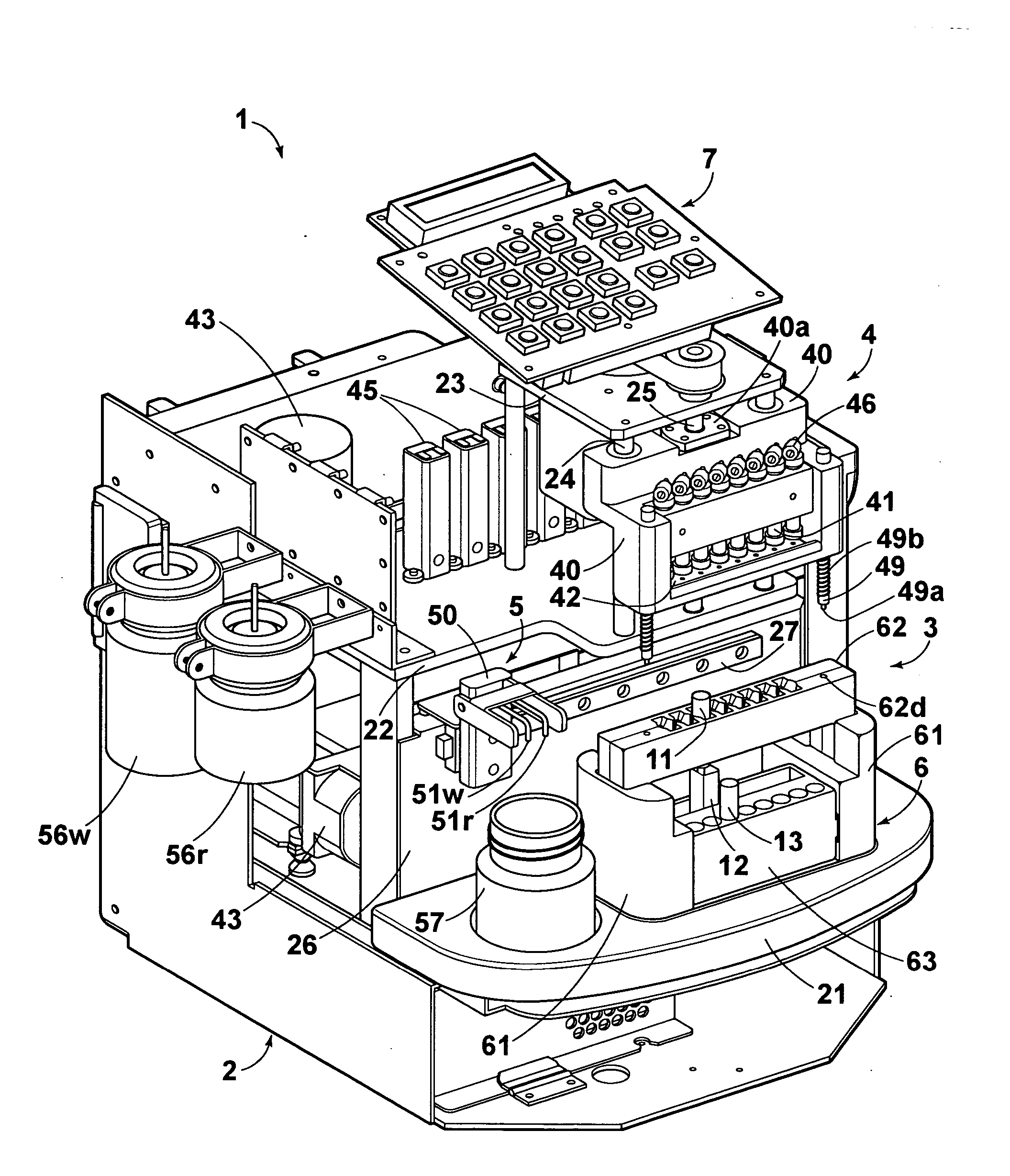
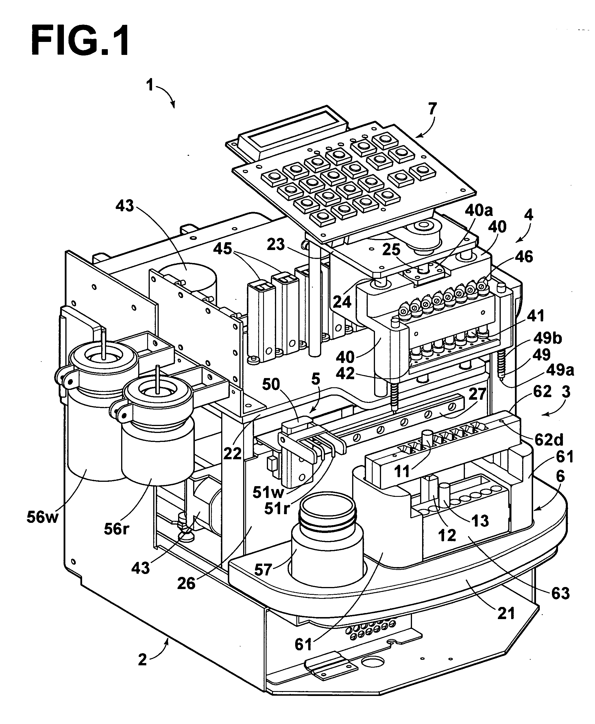
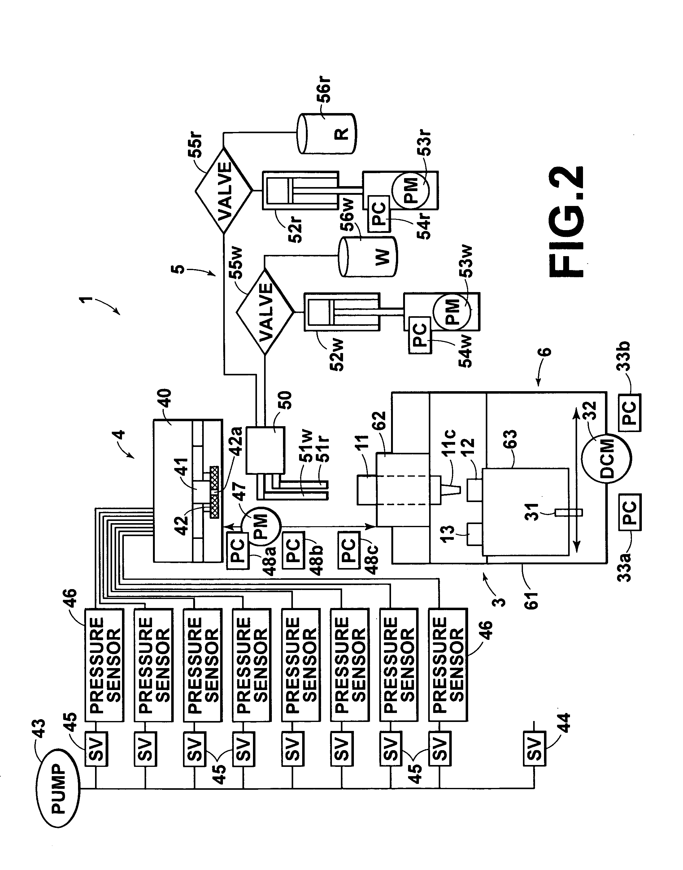
[0063]FIG. 1 is a perspective view showing an embodiment of the extracting apparatus in accordance with the present invention with a cover being removed. FIG. 2 is a block diagram showing mechanisms of the nucleic acid extracting apparatus of FIG. 1. FIG. 3 is a perspective view showing a rack of a loading mechanism. FIG. 4 is a perspective view showing the rack of FIG. 3 in the state in which the rack is being used. FIG. 5 is an explanatory view showing an air system of a pressurized air supplying mechanism. FIG. 6 is an explanatory view showing a control system of the pressurized air supplying mechanism. FIG. 7 is a flow chart showing an example of control of pressurization. FIG. 8 is a graph showing variation in internal pressure within an extracting cartridge. FIGS. 9A to 9G are flow diagrams showing an extracting operation. FIG. 10 is a perspective view show...


PUM

PropertyMeasurementUnit
Pressureaaaaaaaaaa
Internal pressureaaaaaaaaaa

Abstract

A mechanism for introducing pressurized air into an extracting cartridge comprises an air pump, an on-off valve, and a pressure sensor for detecting an internal pressure within the extracting cartridge. The on-off valve is turned on in order to introduce the pressurized air into the extracting cartridge. When the internal pressure detected by the pressure sensor has become equal to a predetermined pressure range for a pressurization upper limit, the on-off valve is turned off in order to confine the area within the extracting cartridge in the pressurized state, the pressure being thereby exerted upon a sample liquid, a washing liquid, or a recovery liquid having been injected into the extracting cartridge.

Description

BACKGROUND OF THE INVENTION [0001] 1. Field of the Invention [0002] This invention relates to an extracting apparatus for extracting a predetermined substance such as a nucleic acid from a sample liquid by use of at least one extracting cartridge provided with a filter member. This invention particularly relates to extraction of the predetermined substance through pressurization of an area within at least one extracting cartridge with pressurized air introduced into the extracting cartridge. [0003] 2. Description of the Related Art [0004] As extracting methods, for example in techniques for extracting a nucleic acid, a centrifugal technique, a technique utilizing magnetic beads, a technique utilizing a filter, and the like, have heretofore been known. [0005] For example, there has been proposed a nucleic acid extracting apparatus utilizing filters. With the proposed nucleic acid extracting apparatus, a plurality of filter tubes, each of which accommodates a filter therein, are set o...

Claims


Application Information

Patent Timeline
IPC IPC(8): G01N1/34G01N1/40G01N35/02
CPCG01N1/34G01N35/026G01N1/405
Inventor FUJIMOTO, KEIICHITORISAWA, NOBUYUKI
Owner FUJIFILM HLDG CORP
Learn More