Electric brake system

Inactive Publication Date: 2005-03-03
ADVICS CO LTD
View PDF7 Cites 10 Cited by
  • Summary
  • Abstract
  • Description
  • Claims
  • Application Information

AI Technical Summary

Benefits of technology

[0013] Accordingly, it is possible to allow the actual control variable for the electric brake to follow the target value with a good response. Furthermore, it is possible to suppress the oscillation phenomenon which generally subsequently occurs due to inertia and elasticity of the motor or the electric brake after the following-up of the target value, and therefore to maintain the stable output state. This in turn makes it

Problems solved by technology

Accordingly, the following-up of the target value of the actuator output by the actual control variable delays, leading to a poor response.
In the brake apparatus disclosed in Japanese Patent Application Laid-open No. 2003-104195, suppression on the rotational speed of the motor makes it impossible to adequately use the potential of the motor.
Accordingly, the following-up of the target value of the actuator output by the actual control variable delays, leading to a poor response.
Therefore, any apparatus used for

Method used


Image

  • Electric brake system
  • Electric brake system
  • Electric brake system

Examples


Example

First Embodiment

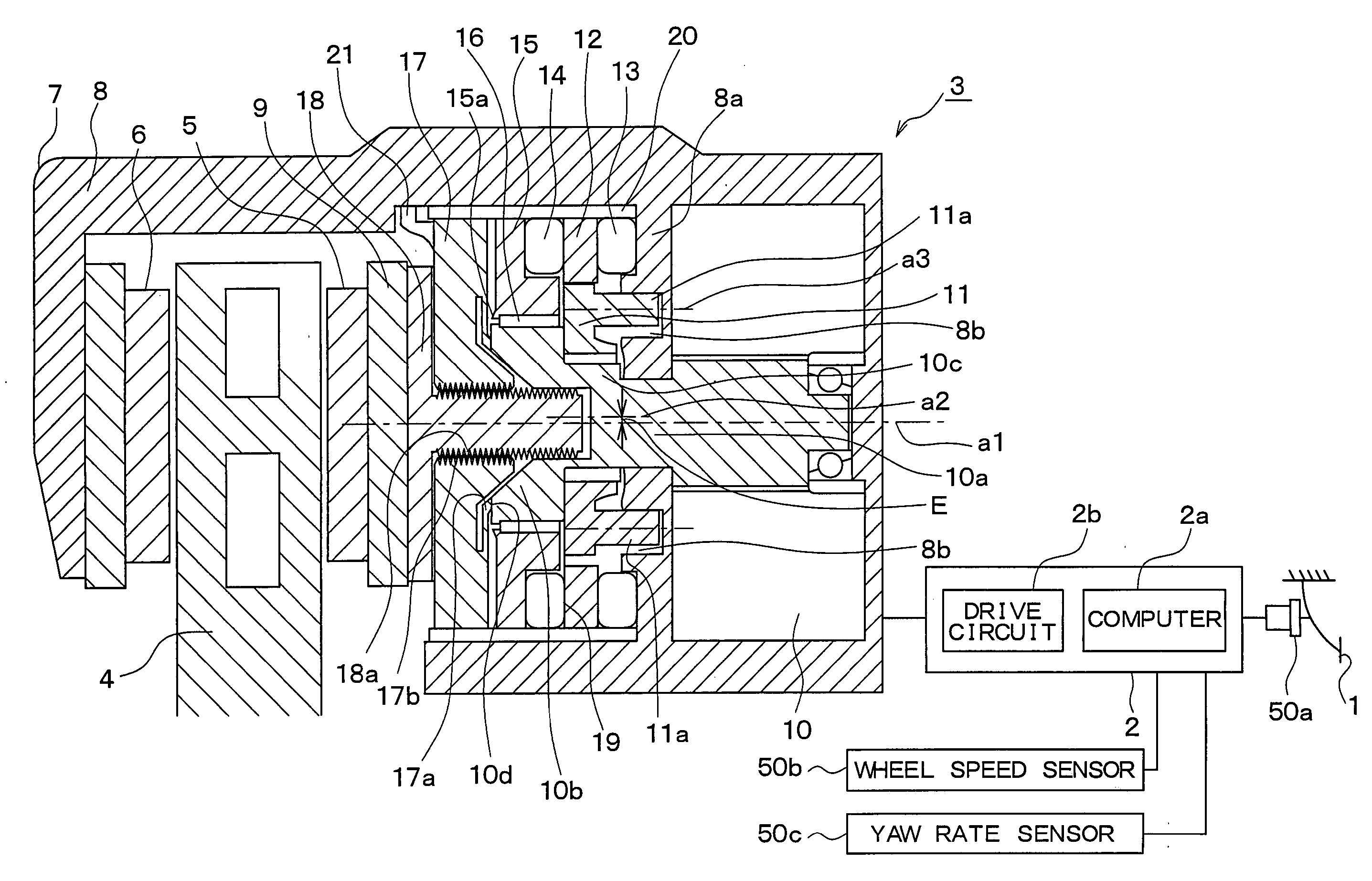
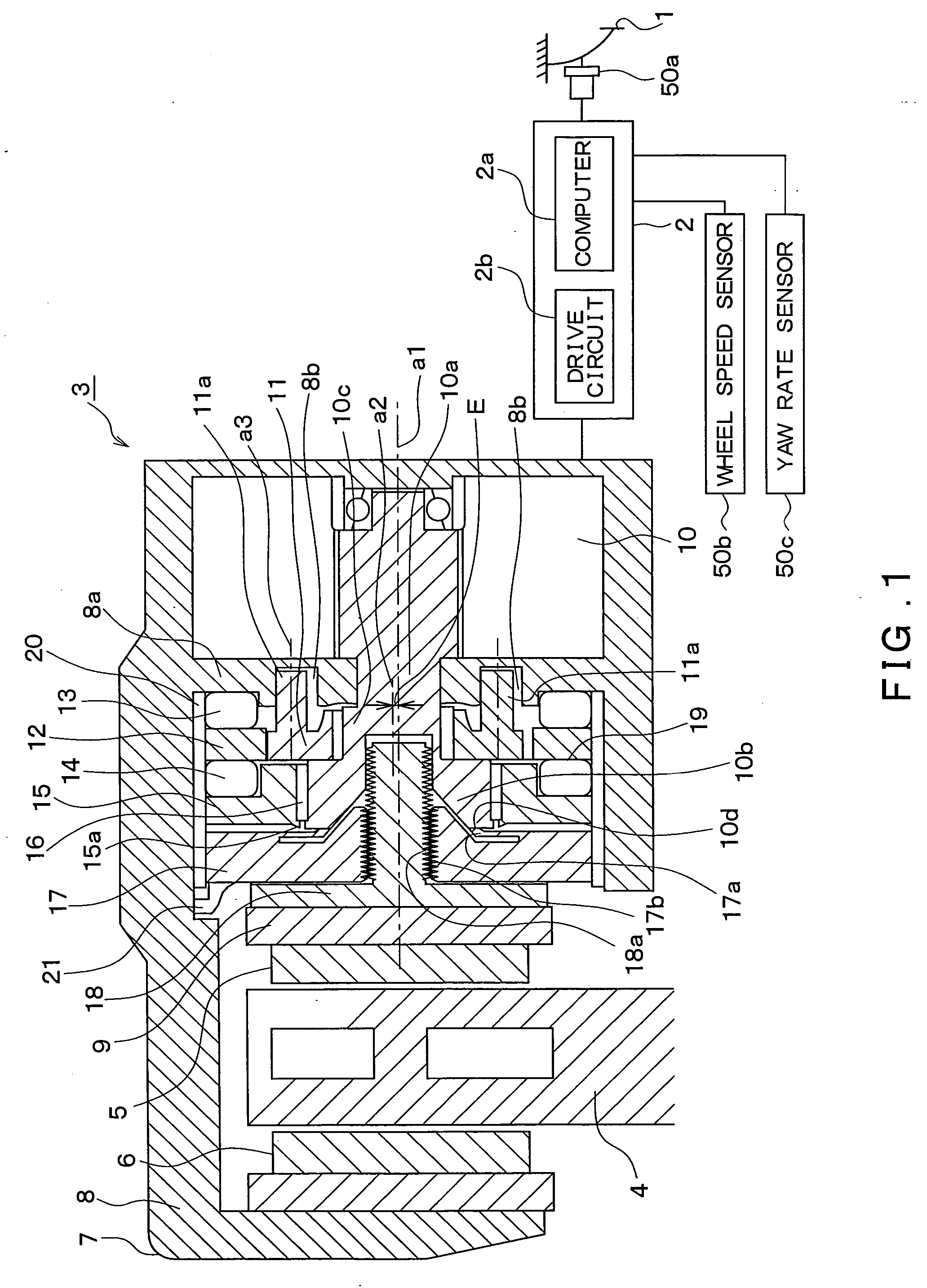
[0020]FIG. 1 illustrates an outline of a structure of an electric brake system to which an embodiment according to the present invention is applied. Hereafter, the structure of the electric brake system will be described with reference to FIG. 1.

[0021] The electric brake system includes a brake pedal 1 corresponding to a brake operating member, an electronic control unit (hereinafter referred to as “ECU”) 2, an electric brake 3 for generating a brake force on each wheel, various sensors 50a to 50c, and the like. The electric brakes 3 are mounted on the respective four wheels, but FIG. 1 representatively illustrates only one of the electric brakes 3 mounted on the four wheels.

[0022] To the brake pedal, 1 a pedal operating sensor 50a is attached for detecting an operation amount of the brake pedal 1, e.g., the pedal depression force or the amount of stroke. A detection signal is sent from the pedal operating sensor 50a to the ECU 2.

[0023] The ECU 2 is equipped with...


PUM


Abstract

The present invention provides an electric brake system in which an actual control variable in the electric brake when overshooting is generated is determined, and the target value is set to a maximum value of the actual control variable in the electric brake when overshooting is generated. Therefore, the target value and the actual control variable will be in agreement with each other before hunting to be generated after overshooting starts. Accordingly, the output of the electric brake is gradually stabilizing at the target value without an oscillation phenomenon as in a related art.

Description

CROSS REFERENCE TO RELATED APPLICATION [0001] This application is based upon and claims the benefit of Japanese Patent Application No. 2003-299895 filed on Aug. 25, 2003, the content of which are incorporated herein by reference. FIELD OF THE INVENTION [0002] This invention relates to an electric brake system for electrically controlling brake pressure corresponding to the amount of operation of the brake operating member. BACKGROUND OF THE INVENTION [0003] Among conventional anti-skid control (ABS) apparatuses that increase / decrease the fluid-chamber capacity by means of linear movement caused by an electric motor, one proposed apparatus is a type in which an instruction current supplied to the motor is determined in accordance with a state variable corresponding to a motor speed as well as a tire slip rate (see Japanese Patent Application Laid-open No. HEI6-72312). This apparatus determines the instruction current supplied to the motor anticipating the speed energy provided by the...

Claims


Application Information

Patent Timeline
IPC IPC(8): B60T8/17B60T13/74F16D65/14F16D65/18
CPCB60T13/741F16D65/18F16D2125/50F16D2125/40F16D2121/24
Inventor ARAKAWA, HARUOYOKOYAMA, TAKAHISATAKESHITA, TAKAYUKI
Owner ADVICS CO LTD
Why Eureka
Try Eureka