Pixelated phase-mask interferometer

a phase-mask interferometer and pixelated technology, applied in the field of interferometry, can solve the problems of chromatic dispersion, compact and less expensive, and all the methods that require relatively complex optical and electronic arrangements, and achieve the effects of reducing the complexity of optical arrangements, avoiding complexity and chromatic dispersion, and increasing the range of operational wavelengths

Active Publication Date: 2005-03-03
ONTO INNOVATION INC
View PDF22 Cites 97 Cited by
  • Summary
  • Abstract
  • Description
  • Claims
  • Application Information

AI Technical Summary

Benefits of technology

While the present invention accomplishes simultaneous phase-shifting with a single pixelated detector, it avoids the complexity and chromatic dispersion that accompanies the prior-art approach of splitting the wavefront into sub-images with diffractive optical elements. The invention provides an improved method and apparatus for performing two-wavelength interferometry by increasing the range of operational wavelengths, eliminating the need to calibrate dispersion-related

Problems solved by technology

These methods all require relatively complex optical and electronic arrangements.
While these methods are more compact and less expensive than multi-camera arrangements, they operate only over a limited wavelength range due to dispersion and chromatic distortion inherent in their design.

Method used


Image

  • Pixelated phase-mask interferometer
  • Pixelated phase-mask interferometer
  • Pixelated phase-mask interferometer

Examples


Embodiment Construction

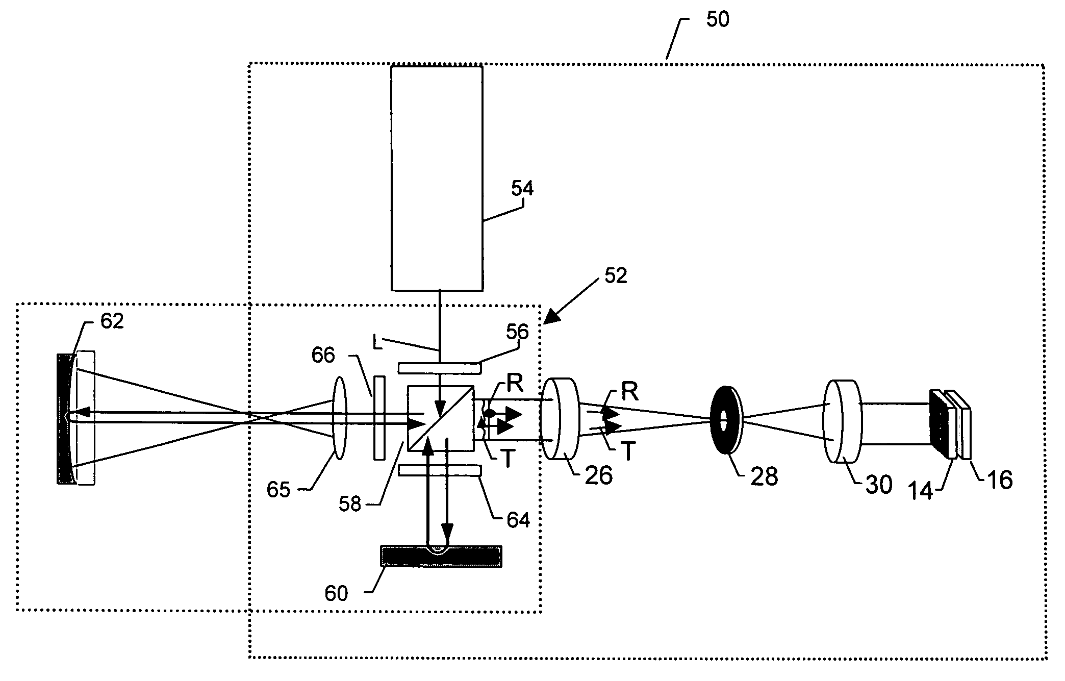
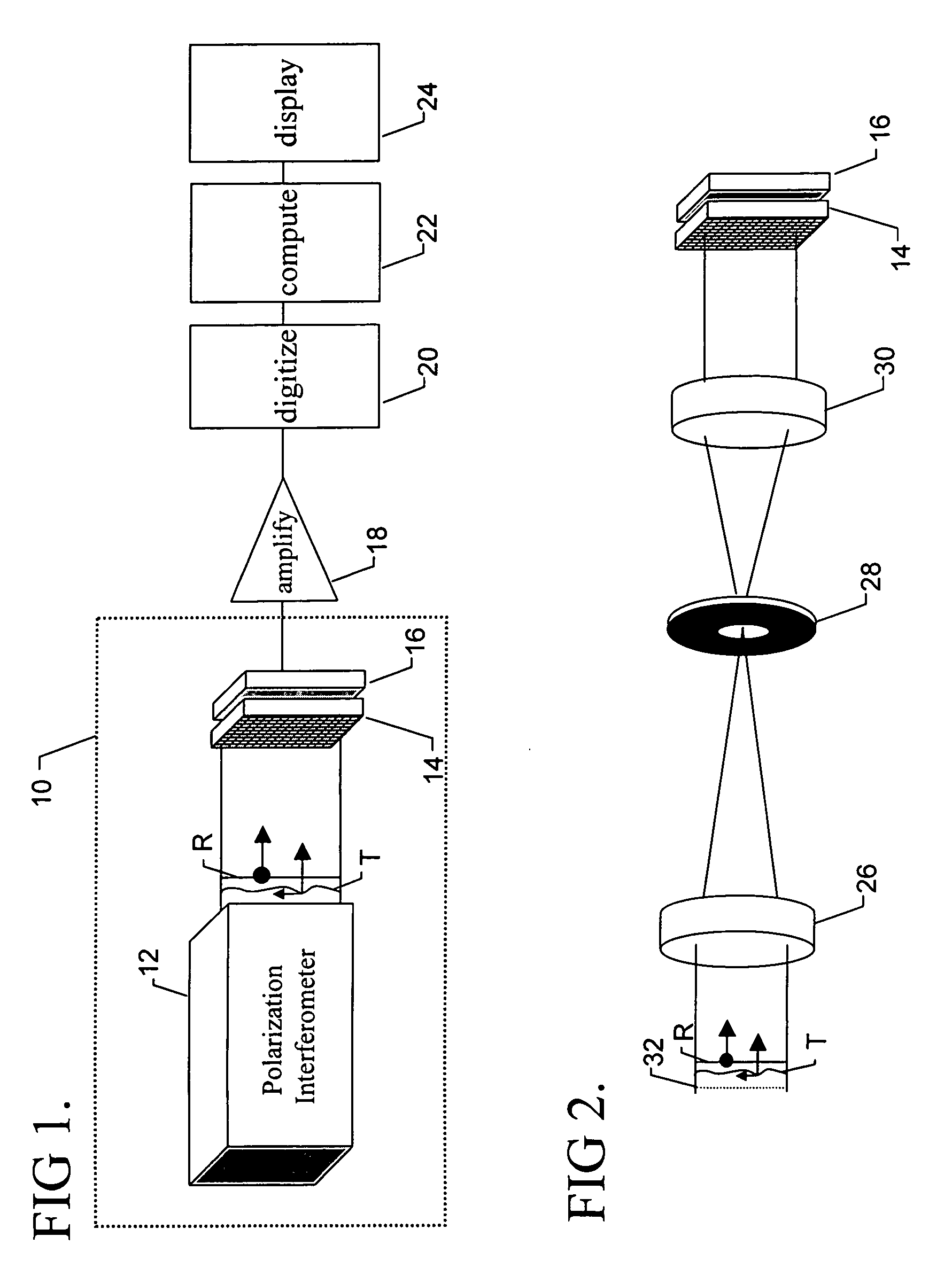
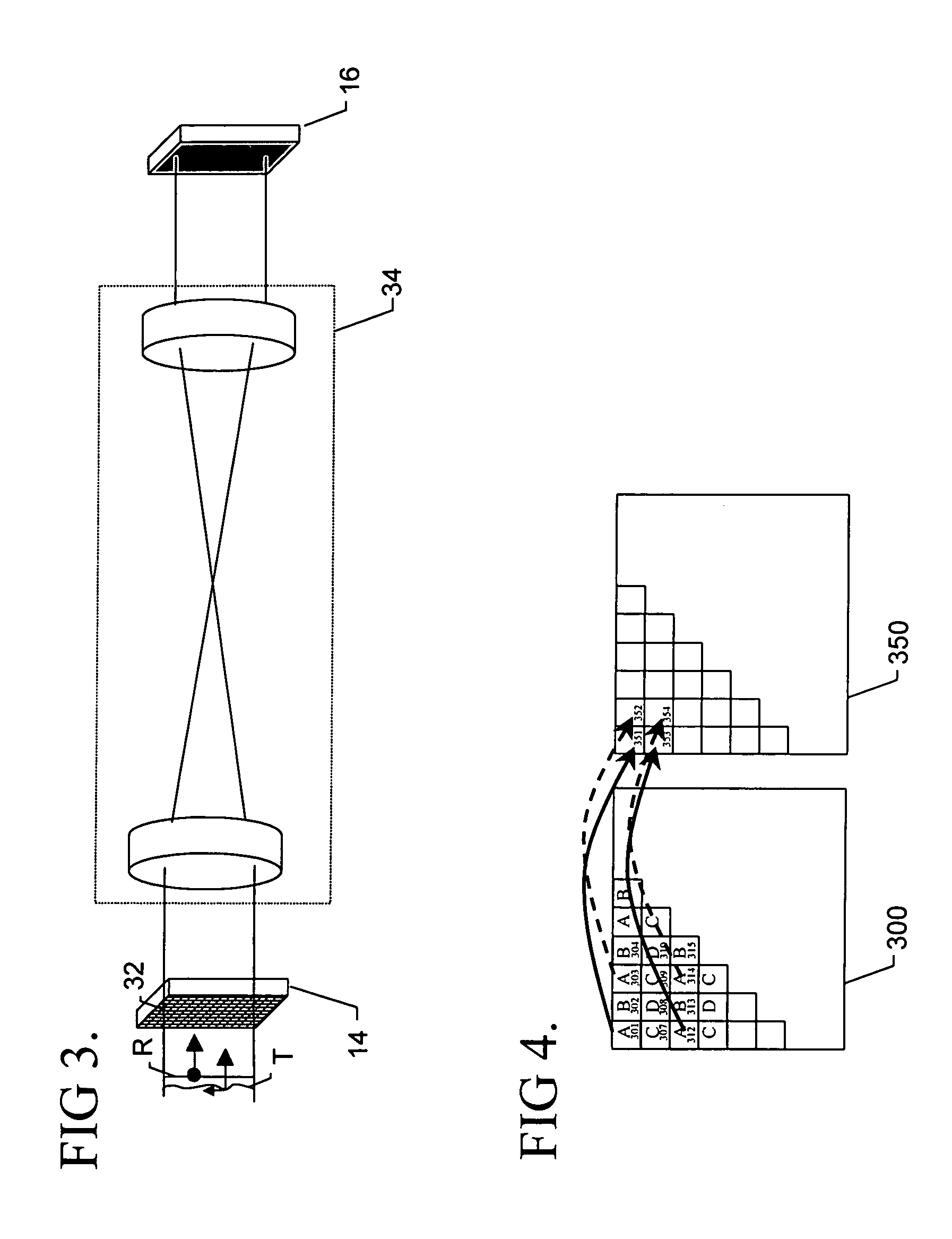
The heart of the invention lies in a pixelated detector with a pixelated phase-mask subdivided into a plurality of sets of phase-mask pixels, such that each set produces a predetermined phase shift between orthogonally polarized test and reference beams. Thus, each set of phase-mask pixels provides a spatially separated intensity pattern (interferogram) on corresponding pixels of the detector. By providing at least three such sets of phase-mask pixels, each associated with a different phase shift, sufficient interferograms are produced to characterize a sample surface using conventional interferometric algorithms. For best results, the phase-mask pixels are preferably distributed uniformly throughout the phase-mask, so that each pixel is surrounded by adjacent pixels belonging to other sets. Similarly, for best resolution, a one-to-one correspondence is preferably used between the phase-mask and the detector pixels.

Thus, various parameters of test objects may be measured by simul...


PUM


Abstract

A phase-difference sensor measures the spatially resolved difference in phase between orthogonally polarized reference and test wavefronts. The sensor is constructed as a pixelated phase-mask aligned to and imaged on a pixelated detector array. Each adjacent pixel of the phase-mask measures a predetermined relative phase shift between the orthogonally polarized reference and test beams. Thus, multiple phase-shifted interferograms can be synthesized at the same time by combining pixels with identical phase-shifts. The multiple phase-shifted interferograms can be combined to calculate standard parameters such as modulation index or average phase step. Any configuration of interferometer that produces orthogonally polarized reference and object beams may be combined with the phase-difference sensor of the invention to provide, single-shot, simultaneous phase-shifting measurements.

Description

BACKGROUND OF THE INVENTION 1. Field of the Invention The present invention relates to interferometry. More particularly, the invention relates to methods and apparatus for rapid measurement of the optical phase-difference between two wavefronts. The invention may be implemented in optical systems that measure various parameters of test objects by generating test and reference waves having orthogonal polarizations. 2. Description of the Related Art Phase-shift interferometry is an established method for measuring a variety of physical parameters ranging from the density of gases to the displacement of solid objects. An interferometric wavefront sensor employing phase-shift interferometry typically consists of a light source that is split into two wavefronts, a reference and test wavefront, that are later recombined after traveling different path lengths. The relative phase difference between the two wavefronts is manifested as a two-dimensional intensity pattern known as an inte...

Claims


Application Information

Patent Timeline
IPC IPC(8): G01BG01B9/02
CPCG01B9/02057G01B9/02022G01B9/02083G01B9/02081G01B2290/70
Inventor BROCK, NEAL J.MILLERD, JAMES E.WYANT, JAMES C.HAYES, JOHN B.
Owner ONTO INNOVATION INC
Why Eureka
Try Eureka