Optical pickup and optical recording and/or reproducing apparatus adopting the same

a technology of optical recording and optical recording, applied in the field of optical recording and/or reproducing apparatus, can solve the problems of low offset generation of tracking error signal tes

Inactive Publication Date: 2005-03-03
TS OPTICS CORP
View PDF2 Cites 35 Cited by
  • Summary
  • Abstract
  • Description
  • Claims
  • Application Information

AI Technical Summary

Benefits of technology

According to still another aspect of the present invention, there is provided a method of suppressing generation of an offset in a tracking error signal due to an initial photodetector balance deviation. The method includes: dividing the light reflected from a recording medium into a central light area and first and second peripheral light areas at respective sides of the central light area; dividing, at first and second central diffraction areas, at least a part of a central light area into two sub-areas in a radial direction and diffracting light to the at the two sub-areas; dividing, at first and second peripheral diffraction areas, a first peripheral light area into two sub-areas in a tangential direction and diffracting light to the two sub-areas; dividing, at third and fourth peripheral diffraction areas, a second peripheral light area into two sub-areas in a second direction and diffract light to the two sub-areas; receiving, at first and second light-receiving portions of a photodetector, the light diffracted into a +1st or −1st order light by the first and second central diffraction areas and converting the first light into an electrical signal; and receiving, at third through sixth light-receiving portions, a +1st order light and / or a −1st order light diffracted by the first through fourth peripheral diffraction areas. The diffraction unit divides the first light reflected by the recording medium into at least 6 light areas and diffracting the at least 6 light areas.

Problems solved by technology

As a result, when the conventional tracking method disclosed in the above publication is used, a tracking error signal TES in which an offset generation is low even upon a shift of the objective lens can be detected.
However, when there exists an initial photodetector balance offset, the PP signal has an offset, and accordingly, a tracking error signal TES has a larger offset.
Further, the conventional optical pickup may record data on a recording medium while being detracked due to an offset of the tracking error signal.

Method used


Image

  • Optical pickup and optical recording and/or reproducing apparatus adopting the same
  • Optical pickup and optical recording and/or reproducing apparatus adopting the same
  • Optical pickup and optical recording and/or reproducing apparatus adopting the same

Examples


Embodiment Construction

Reference will now be made in detail to embodiments of the present invention, examples of which are illustrated in the accompanying drawings, wherein like reference numerals refer to the like elements throughout. The embodiments are described below in order to explain the present invention by referring to the figures.

FIG. 7A illustrates light received by a photodetector 19 when there is no initial photodetector balance offset. FIG. 7B illustrates the shift of light received by the photodetector 19 when there is an initial photodetector balance deviation of d1. FIGS. 7A and 7B illustrate that the CFF signal is not affected by an initial photodetector balance offset when a CFF signal is detected using the CFF tracking method.

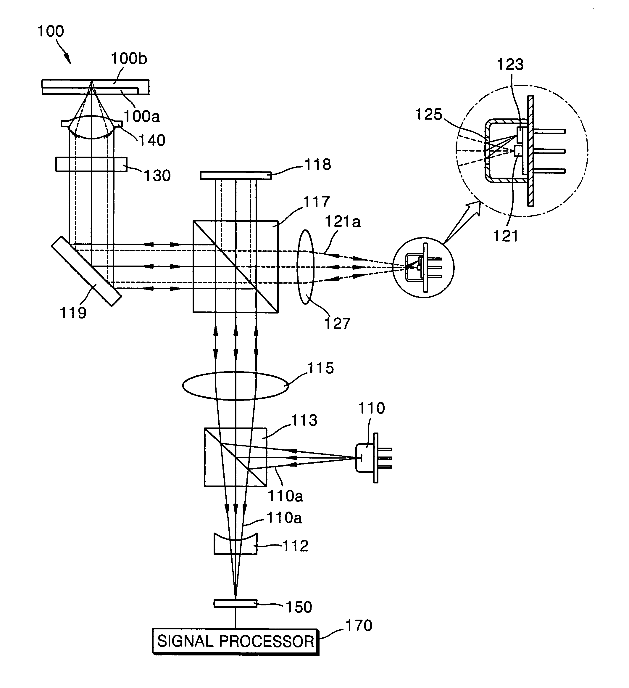
The optical system of FIGS. 7A and 7B corresponds to a part of an optical pickup that can use the CFF tracking method. The optical system of FIGS. 7A and 7B includes a hologram 15, formed to divide light reflected by a recording medium 11 into two parts, and t...


PUM

PropertyMeasurementUnit
wavelengthaaaaaaaaaa
red wavelengthaaaaaaaaaa

Abstract

An optical pickup which, when a first light reflected by a recording medium is divided into a central light area and first and second peripheral light areas at both sides of the central light area, divides the first light reflected by the recording medium into at least 6 light areas, and the at least 6 light areas are independently detected from first through sixth light-receiving portions of a photodetector. Hence, the photodetector can detect a tracking error signal whose offset generation due to a shift of an objective lens is insensitive and whose offset generation due to an initial photodetector balance deviation is depressed.

Description

CROSS-REFERENCE TO RELATED APPLICATION This application claims the benefit of Korean Patent Application No. 2003-59143, filed on Aug. 26, 2003, in the Korean Intellectual Property Office, the disclosure of which is incorporated herein by reference. BACKGROUND OF THE INVENTION 1. Field of the Invention The present invention relates to an optical recording and / or reproducing apparatus, and more particularly, to an optical pickup capable of preventing a tracking offset from being generated due to a shift of an objective lens and an initial balance deviation of a photodetector and an optical recording and / or reproducing apparatus adopting the optical pickup. 2. Description of Related Art In high capacity recording and / or reproduction, accurate detection of a focusing and / or tracking error signal is necessary for performing a stable servo function. Generally, an optical pickup is composed of a light source, an objective lens, and a light-receiving optical system. The objective lens ...

Claims


Application Information

Patent Timeline
Patent Type & Authority Applications(United States)
IPC IPC(8): G11B7/00G11B7/09G11B7/125G11B7/13G11B7/135
CPCG11B7/0901G11B7/094G11B7/1275G11B2007/0006G11B7/1353G11B7/1381G11B7/131G11B7/09
Inventor PARK, SUN-MOOKJUNG, JIN-HOSEONG, PYON-YONG
Owner TS OPTICS CORP
Why Eureka
Try Eureka