Supercharge Your Innovation With Domain-Expert AI Agents!

Compressor surge prevention via distinct blade shapes

a technology of distinct blades and compressors, applied in the direction of positive displacement liquid engines, piston pumps, liquid fuel engines, etc., can solve the problems of external devices such as pneumatic tools, seizing and abruptly stopping working, compressor failure, impeller stalling or failing,

Inactive Publication Date: 2005-03-03
GM GLOBAL TECH OPERATIONS LLC
View PDF9 Cites 7 Cited by
  • Summary
  • Abstract
  • Description
  • Claims
  • Application Information

AI Technical Summary

Benefits of technology

[0010] The impeller is operable to capture an air stream near a leading edge of each blade and compress the air stream for use in an external system. By defining each blade shape as a function of (R) only, the impeller is capable of functioning under conditions where inlet mass flow is at, or approaching, zero, and is therefore operable to prevent surge.

Problems solved by technology

As can be appreciated, interruption of a compressor can cause external devices, such as pneumatic tools, to seize and abruptly stop working.
A common occurrence of such compressor failure is caused by surge.
Under such conditions, flow separation of the inlet air stream can cause a stalled flow to be received by the impeller, thereby causing the impeller to stall or fail.
Such conventional systems include positive displacement compressors with low performance and high noise levels, compressors with modified casings or housings operable to delay the onset of stall, and variable geometry inlet guide vanes.
In each of the foregoing systems, a significant amount of power is wasted driving a very unsteady or stalled flow without actually preventing surge.
In this manner, conventional systems suffer from the disadvantage of requiring multiple systems to delay the onslaught of surge, thereby increasing the complexity and cost of the overall system without actually preventing surge.
Additionally, because conventional systems merely delay the onslaught of surge, such conventional systems are unable to provide a constant stream of pressurized fluid as such systems are unable to perform under reduced flow conditions.

Method used


Image

  • Compressor surge prevention via distinct blade shapes
  • Compressor surge prevention via distinct blade shapes
  • Compressor surge prevention via distinct blade shapes

Examples


Embodiment Construction

[0022] The following description of the preferred embodiments is merely exemplary in nature and is in no way intended to limit the invention, its application, or uses.

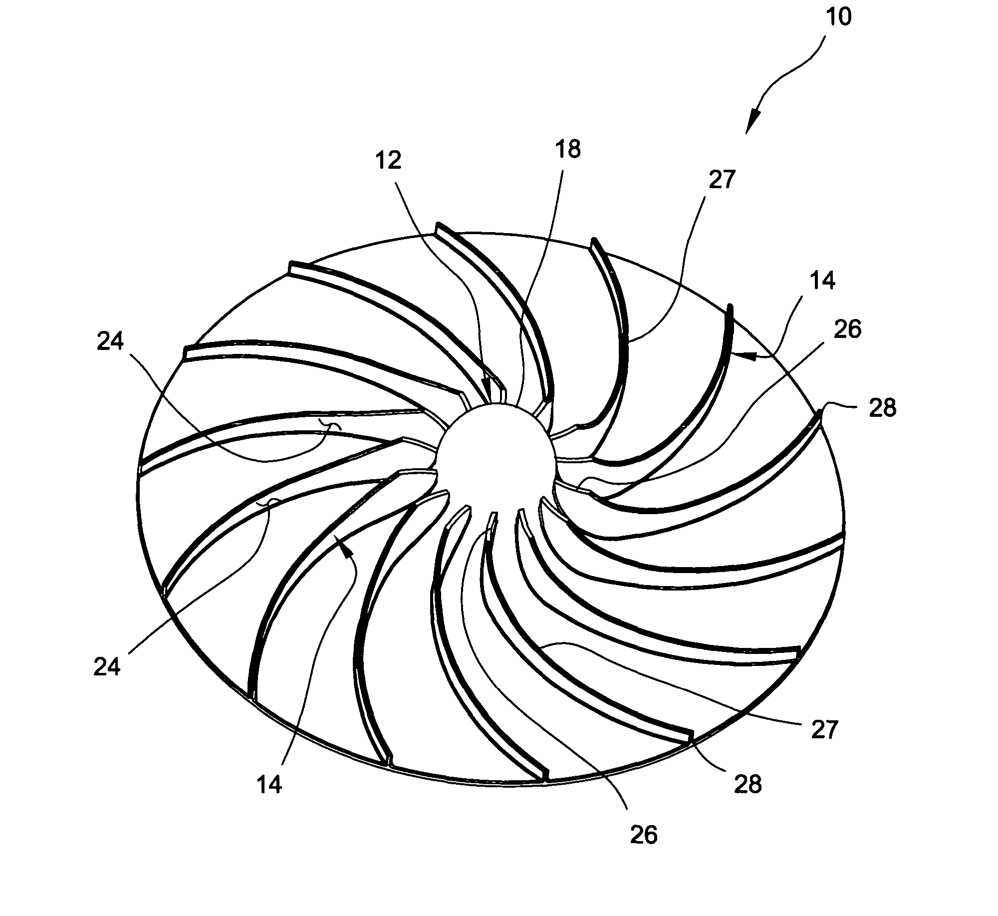
[0023] With reference to the figures, an impeller 10 is provided and includes a hub 12 and a plurality of blades 14 radially extending therefrom. The impeller 10 is operable to capture an air flow through cooperation between the plurality of blades 14 and the hub 12 to compress the air flow and deliver a pressurized air stream as the impeller 10 rotates about a central axis of rotation 16.

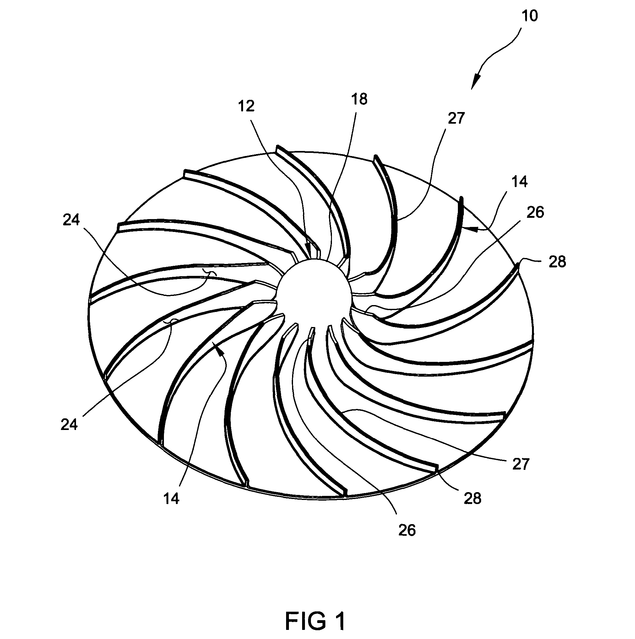
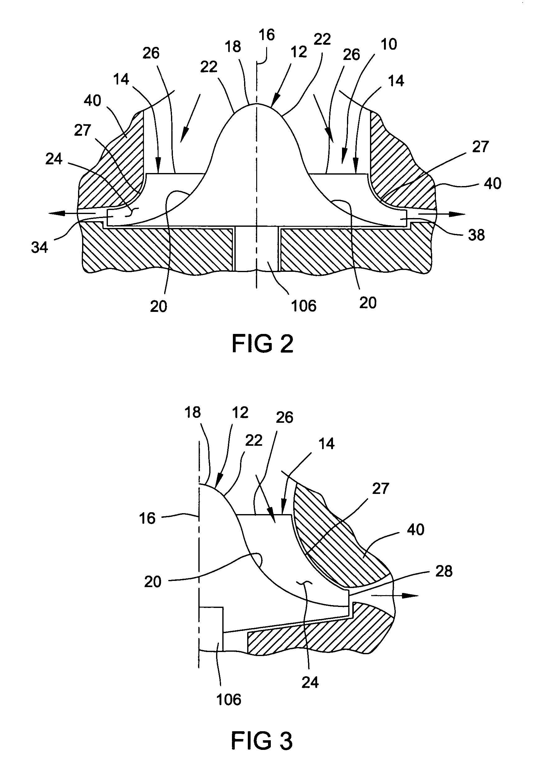
[0024] With reference to FIG. 1, the impeller 10 is shown to include a generally circular shape having the hub 12 disposed coaxially with the axis of rotation 16. The hub 12 includes a tip 18 and a hub contour 20 formed proximate each blade 14, as best shown in FIGS. 2 and 3. The hub tip 18 includes a generally arcuate surface 22 for distributing a received air flow to each of the plurality of blades 14.

[0025] With reference to FIG...


PUM


Abstract

A compressor includes a vaneless diffuser, a volute in fluid communication with the diffuser, and an impeller operable to compress a fluid stream and direct the fluid stream to the diffuser. The impeller includes a hub having an axis of rotation and a plurality of blades extending therefrom. The blades include a surface defined by an axial direction (Z), a radius (R) defined from the axis of rotation of the hub, and a polar angle (⊖), whereby ⊖ is substantially defined by the equation: ⊖=a*[natural logarithm of (R)]+b.

Description

FIELD OF THE INVENTION [0001] The present invention relates to impellers for compressors and pumps and the like, and more particularly, to an improved blade design for an impeller. BACKGROUND OF THE INVENTION [0002] Impellers are widely used in a variety of applications to compress a fluid. For example, impellers are often used in air compressor applications for use in generating compressed air to power pneumatic tools and the like. Alternatively, impellers are used to compress a fluid for use in a pressurized system such as in supplying a pressurized fluid stream for use on a fire truck or pumping station. Further yet, such impellers are commonly used in the design and operation of aircraft engines, whereby a compressed fluid stream is provided via an impeller to propel an airplane in a desired direction. In any of the foregoing applications, it is desirable to provide an impeller capable of operating under varying flow conditions to provide a continuous supply of pressurized fluid...

Claims


Application Information

Patent Timeline
IPC IPC(8): F04D29/28F04D29/30
CPCF04D29/30F04D29/284
Inventor JARRAH, YOUSEF M.
Owner GM GLOBAL TECH OPERATIONS LLC
Features
  • R&D
  • Intellectual Property
  • Life Sciences
  • Materials
  • Tech Scout
  • Unparalleled Data Quality
  • Higher Quality Content
  • 60% Fewer Hallucinations
Learn More