Air flow monitoring and control system with reduced false alarms

a technology of air flow monitoring and control system, which is applied in ventilation systems, heating types, stoves or ranges, etc., can solve the problems significant air being pulled from the interior of the building and exhausted to the atmosphere, and it is no longer feasible to depend on leakage around and through windows and doors to replace the extracted air flow. , to achieve the effect of reducing air flow

Inactive Publication Date: 2005-03-03
CORNELL RES FOUNDATION INC
View PDF13 Cites 40 Cited by
  • Summary
  • Abstract
  • Description
  • Claims
  • Application Information

AI Technical Summary

Benefits of technology

[0016] In a preferred embodiment, the system is implemented on a facility-wide basis. Alarms on a plurality of fume hoods or similar devices communicate with an ASC, which is, in turn connected to a facility network bus. At least one air handler is also connected to the bus, providing signals for its status and accepting commands for its operation. The air handler provides control for variable speed drives on the fume h

Problems solved by technology

Failure of a fan motor or plugging of air filters, inlets or outlets, could lead to a dangerous diminution in air flow.
This has resulted in a number of problems in laboratory or factory buildings and other similar facilities in which there are a large number of devices such as lab hoods, paint booths, assembly line process equipment using chemicals, stove hoods, etc., extracting conditioned air from the building.
When these devices are on, a significant amount of air is pulled from the interior of the building and exhausted to atmosphere.
With the building being made as air-tight as possible, it is no longer feasible to depend on leaks around and through windows and doors to replace the extracted air flow.
If the hoods are left on when there is no laboratory activity, a great deal of energy is wasted drawing in outside air through the air handlers, conditioning it, and blowing it out through the roof through the hoods.
However, if t

Method used


Image

  • Air flow monitoring and control system with reduced false alarms
  • Air flow monitoring and control system with reduced false alarms
  • Air flow monitoring and control system with reduced false alarms

Examples


Embodiment Construction

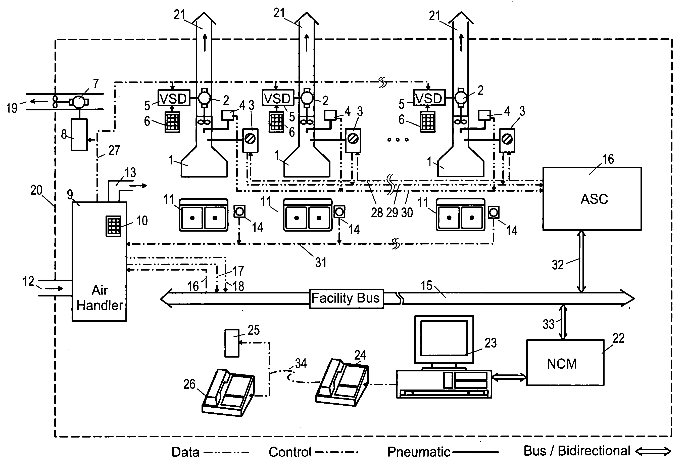
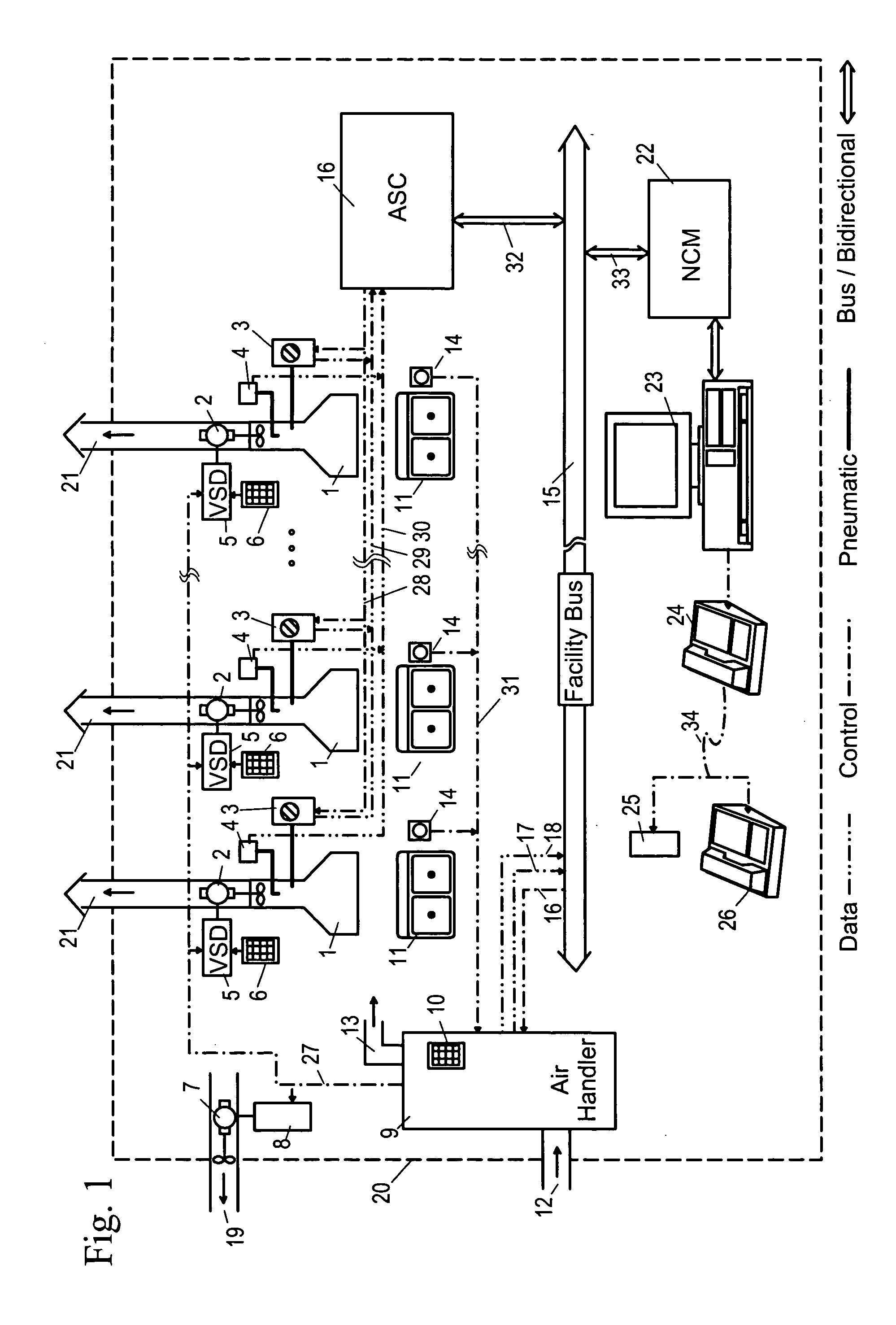
[0020]FIG. 1 shows a block diagram of the invention, as it would be implemented in a laboratory building (20) having a number of fume hoods (1). It will be understood that the invention may be used in other applications than fume hoods, wherever there are apparatus which exhaust air from a building, such as spray booths, assembly line ventilators for chemical baths, range or industrial cooking hoods, etc. Also, although the example of FIG. 1 is shown with a single air handler with three associated fume hoods and an exhaust fan, the invention may also be used with any mixture of air handlers, exhaust devices, building zones, etc.

[0021] Referring to FIG. 1, the dashed line represents a laboratory building (20) or possibly an air handling zone within a larger facility. Outside air (12) is drawn into air handler (9), heated or cooled as required (and possibly filtered, humidified or de-humidified depending on individual building needs), and conditioned air (13) is sent through the norm...


PUM


Abstract

An air flow monitoring and control system with reduced false alarms includes an alarm sensor for monitoring air flow in a fume hood or the like, set to provide a warning if air flow drops below a predetermined amount. A local controller monitors the alarm, and disables it when the hood is set to reduced air flow, whether by a local timer or by command of a central control system. Optionally, the controller itself can operate a variable speed drive to reduce air flow on a timed basis, and the controller can communicate with facility management through a dialer or the Internet, or can interface with a central control for the facility through a facility bus.

Description

REFERENCE TO RELATED APPLICATIONS [0001] This application claims an invention which was disclosed in Provisional Application No. 60 / 495,226, filed Aug. 14, 2003, entitled “AIR FLOW MONITORING AND CONTROL SYSTEM WITH REDUCED FALSE ALARMS”. The benefit under 35 USC §119(e) of the U.S. provisional application is hereby claimed, and the aforementioned application is hereby incorporated herein by reference in its entirety.BACKGROUND OF THE INVENTION [0002] 1. Field of the Invention [0003] The invention pertains to the field of monitoring and control of air flow handling devices such as laboratory fume hoods. More particularly, the invention pertains to methods of avoiding false alarms in air flow monitoring systems for air handling systems. [0004] 2. Description of Related Art [0005] Laboratory fume hoods have long been used to extract fumes from the vicinity of laboratory workers. Typically, fume hoods provide an enclosure around and above the experimental area or laboratory table, from...

Claims


Application Information

Patent Timeline
IPC IPC(8): F24F11/00
CPCF24F11/0079Y02B30/746F24F2011/0067F24F11/0086F24F11/30F24F11/54F24F11/77Y02B30/70F24F11/38
Inventor SHABEN, WILLIAM A.
Owner CORNELL RES FOUNDATION INC
Why Eureka
Try Eureka