Chair massager

a chair massager and massage technology, applied in the field of chair massagers, to achieve the effect of maximizing the combination

Inactive Publication Date: 2005-03-03
KIM HAKJIN
View PDF37 Cites 34 Cited by
  • Summary
  • Abstract
  • Description
  • Claims
  • Application Information

AI Technical Summary

Benefits of technology

[0004] The present invention is contrived to overcome the conventional disadvantages. Accordingly, an object of the invention is to provide a chair massager employing a therapeutic massaging

Problems solved by technology

A disadvantage of such conventional arts is an optimal combination of the lengthwise

Method used


Image

  • Chair massager
  • Chair massager
  • Chair massager

Examples


Embodiment Construction

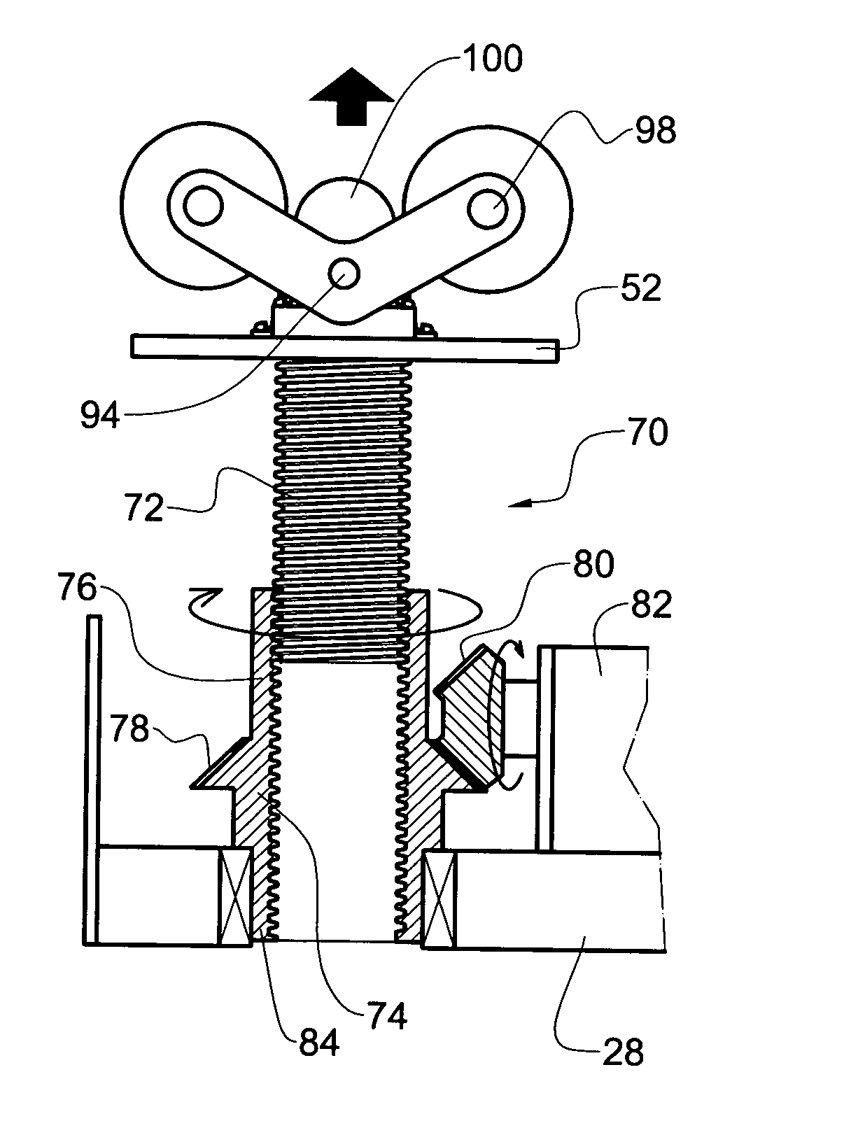
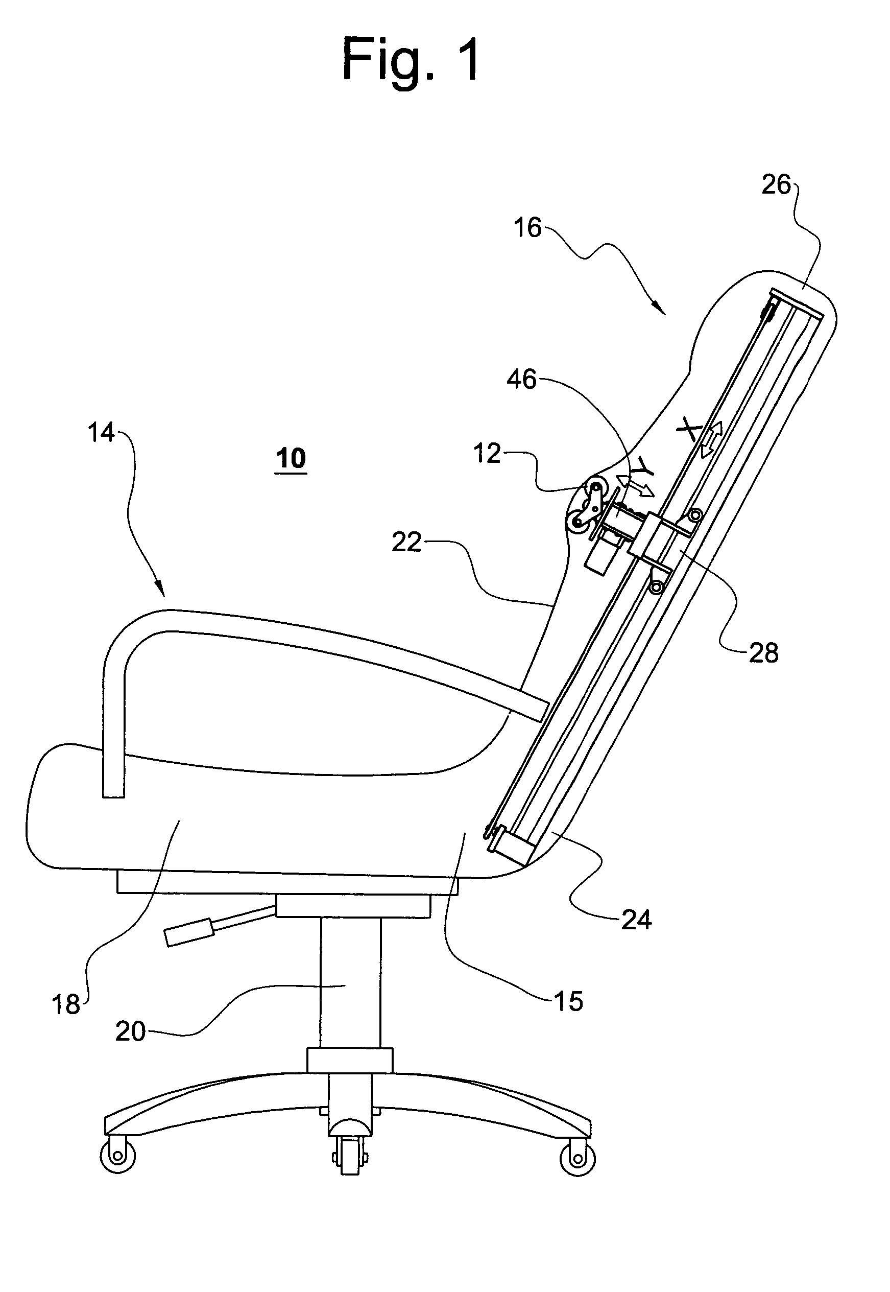
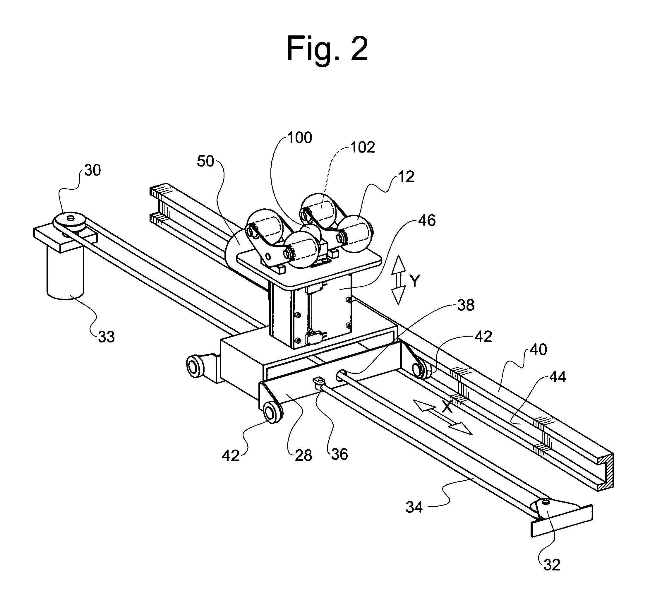
[0021]FIG. 1 shows a brief construction of a chair massager 10 according to a preferred embodiment of the present invention. FIG. 2 shows a mechanism of a lengthwise reciprocation and a forwardly reciprocal movement of massage bumps 12, and FIG. 3 shows a detailed mechanism of the forwardly reciprocal movement. As shown therein, the chair massager 10 includes a base 14 and a back support 16 to place a user's back and neck thereon when the user is seated in the base. The base 14 includes a base cushion 18 and a lower support 20.

[0022] The back support 16 has a cover 22, first and second ends 24, 26. The first end 24 is fixed to the base 14. Specifically, the first end 24 serving as a lower end of the back support 16 is controllably connected to a rear portion 15 of the base 14. In this construction, a rider 28 is provided within the back support 16 to make a lengthwise reciprocal movement X between the first and second ends 24, 26 of the back support 16. In a preferred embodiment, a...


PUM


Abstract

A chair massager comprises a base, a back support to place a user's back and neck thereon when the user is seated in the base. The back support has a cover, first and second ends with the first end fixed to the base. A rider makes a lengthwise reciprocal movement between the first and second ends of the back support, and a lifter liftedly engaged to the rider makes a forward reciprocal movement perpendicular to the lengthwise reciprocal movement. Massage bumps veiled by the cover and attached atop the lifter massage along the user's back and neck by the relative movements of the rider and lifter.

Description

BACKGROUND OF THE INVENTION [0001] The invention relates generally to a massaging device. More particularly, the present invention relates to an improved chair massager capable of efficiently treating bodily malfunctions such as back pain and gastrointestinal weakness by applying a therapeutic massaging treatment along the back and neck of a patient resting on the massager whose massaging bumps are to massage along the patient's spinal cord and neck in a double reciprocation mode. [0002] Conventional massaging chairs adopting spinal massaging mechanism are disclosed to employ a vertical or lengthwise reciprocation and massage balls attached to a mounting member that allows the massage balls to make the vertical reciprocation along a user's back and neck. A disadvantage of such conventional arts is an optimal combination of the lengthwise reciprocation and the pushing momentum of the massage balls toward the user's back. Such pushing momentum needs to be optimally controlled dependin...

Claims


Application Information

Patent Timeline
IPC IPC(8): A61H1/00A61H15/00A61H37/00
CPCA61H15/0078A61H2201/0149A61H2205/081A61H2205/04A61H2201/1669
Inventor KIM, HAKJIN
Owner KIM HAKJIN
Why Eureka
Try Eureka