Bearing and composite structure

a composite structure and bearing technology, applied in the direction of bearings, shafts, coatings, etc., can solve the problems of reduced service life, increased friction, undesired stiffness or friction, etc., to prolong the service life of the bearing surface or other surface, reduce friction, and minimize wear or abrasion

Inactive Publication Date: 2005-03-03
UNIV DUISBURG ESSEN
View PDF36 Cites 101 Cited by
  • Summary
  • Abstract
  • Description
  • Claims
  • Application Information

AI Technical Summary

Benefits of technology

[0007] The present invention is based on the object of providing a bearing, a composite structure, an implant and a method for producing a bearing or composite structure such that the wear or abrasion can be minimized or at least can be reduced, that the formation of particles or at least the emergence of particles can be reduced and / or that the friction can be reduced, it being possible in particular for the service life of the bearing surface or other surface to be prolonged.

Problems solved by technology

With each of these, particle formation is especially problematical and, in the case of sliding bearings in particular, may lead to undesired three-body abrasion as it is known (bearing surface / particle / counterbearing surface).
This may result in particular in an undesired formation of scratches, grooves or the like in the bearing surface and the counterbearing surface, with the consequence of a reduction in the service life.
Furthermore, this may lead to undesired stiffness or an increase in friction.
The particle formation mentioned is particularly critical, since particles which become detached may lead to undesired side-effects in a body in which the implant is implanted.

Method used


Image

  • Bearing and composite structure
  • Bearing and composite structure
  • Bearing and composite structure

Examples


Embodiment Construction

[0027] In the figures, the same designations are used for identical or similar parts, corresponding or comparable advantages and properties being achieved even if the description is not repeated for reasons of simplification.

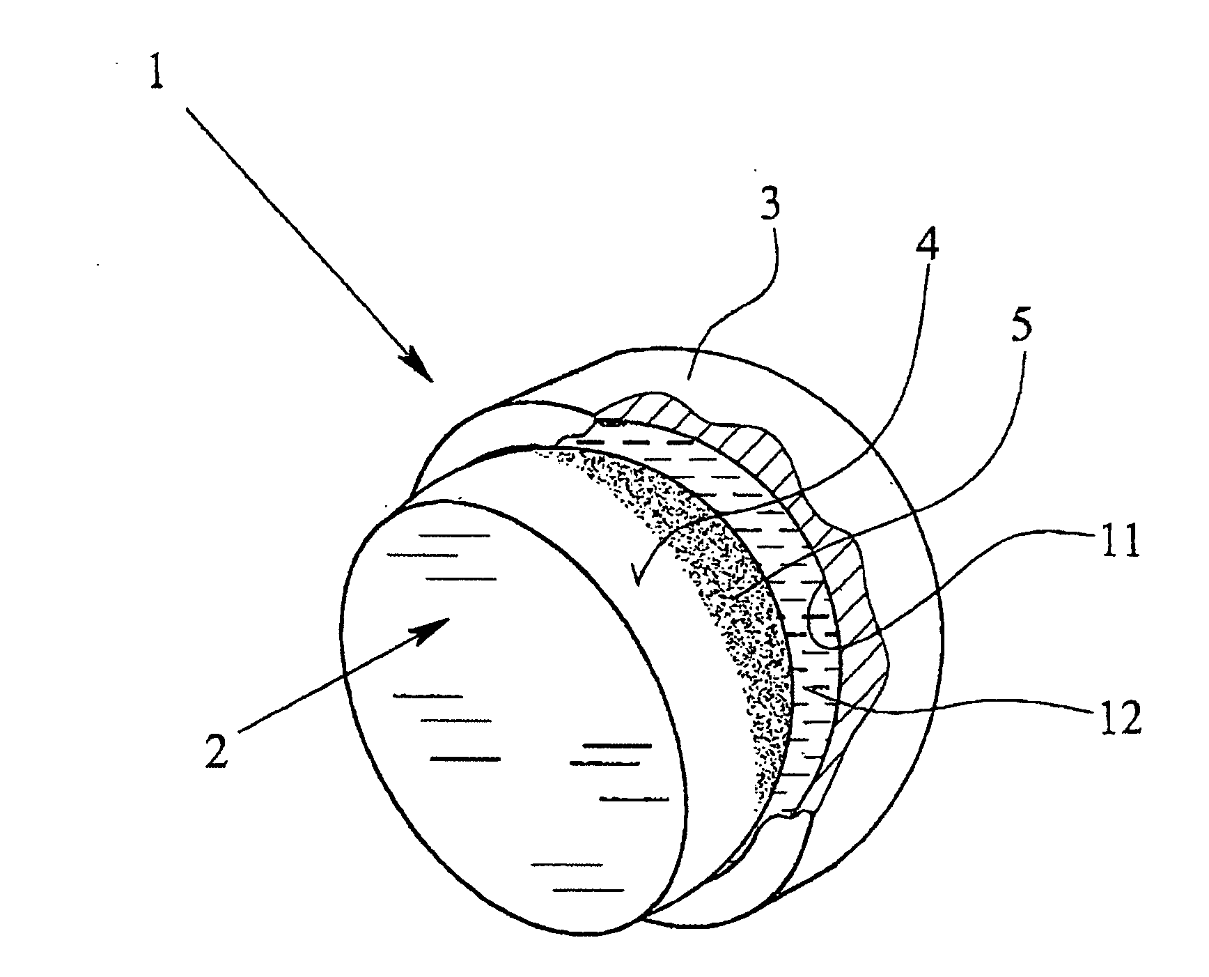
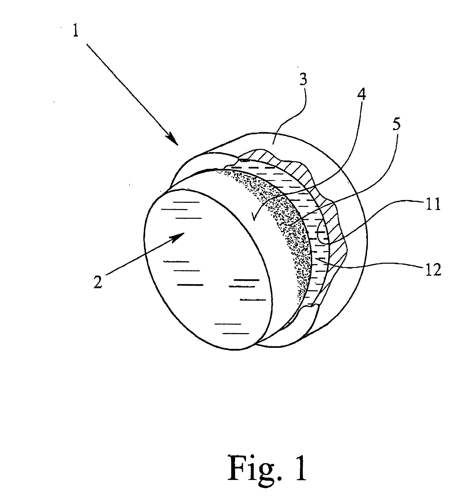
[0028]FIG. 1 shows, in a schematic representation a proposed bearing 1, which in the case of the example represented is formed as a sliding bearing. It may, however, also be some other bearing, such as a roller or rolling bearing.

[0029] The bearing 1 represented has a bearing head 2 and an assigned bearing shell 3, which for illustrative reasons are represented in FIG. 1 in the state in which they have been moved apart from each other. For purposes of illustration, the bearing shell 3 is also represented in section.

[0030] Instead of the formation as a bearing head 2 and bearing shell 3, the bearing elements assigned to each other may also have some other form, adapted to the respective intended use. In particular, a sliding and / or rolling mounting may be inte...


PUM

PropertyMeasurementUnit
peak-to-valley heightaaaaaaaaaa
diameteraaaaaaaaaa

Abstract

A bearing, a composite structure, an implant and a method for producing a bearing with a micro-rough bearing surface are proposed. An improvement in the bearing properties—minimization of particle formation and reduction of friction—and a universally usable composite structure are achieved by the surface of the bearing or of the composite structure being roughened by etching and possibly provided with a coating, preferably consisting of plastic.

Description

BACKGROUND OF THE INVENTION [0001] 1. Field of the Invention [0002] The present invention relates to a bearing, with a micro-rough bearing surface, a composite structure with a micro-rough surface, an implant with a bearing and a method for producing a bearing or a composite structure. [0003] 2. Description of Related Art [0004] In the case of a bearing with a bearing surface, in particular a sliding bearing, a long service life with low friction is desired. Bearing surfaces made of metal, ceramic or plastic are frequently used. [0005] With each of these, particle formation is especially problematical and, in the case of sliding bearings in particular, may lead to undesired three-body abrasion as it is known (bearing surface / particle / counterbearing surface). This may result in particular in an undesired formation of scratches, grooves or the like in the bearing surface and the counterbearing surface, with the consequence of a reduction in the service life. Furthermore, this may lead...

Claims


Application Information

Patent Timeline
Patent Type & Authority Applications(United States)
IPC IPC(8): A61F2/00A61F2/30A61F2/32A61F2/34A61F2/36A61F2/46A61L27/50F16C33/14F16D3/48
CPCA61F2/30767F16C2240/40A61F2/32A61F2/34A61F2/36A61F2/3609A61F2/3662A61F2/468A61F2002/30016A61F2002/30047A61F2002/30321A61F2002/30322A61F2002/30673A61F2002/30685A61F2002/30838A61F2002/3084A61F2002/30925A61F2002/30934A61F2002/345A61F2002/3611A61F2002/3625A61F2250/0019A61F2250/0025A61F2250/0026A61F2250/005A61F2310/00017A61F2310/00023A61F2310/00029A61F2310/00059A61F2310/00179A61F2310/00203A61F2310/00215A61F2310/00604A61L27/50A61L2400/18F16C33/14F16D3/48A61F2/30771F16C2220/68F16C2316/10F16C11/0604F16C2240/54A61F2002/30004
Inventor WAGENER, SVENFISCHER, ALFONS
Owner UNIV DUISBURG ESSEN
Why Eureka
Try Eureka