Optical sensor with co-located pressure and temperature sensors

a technology of optical sensors and pressure and temperature sensors, applied in the field of optical sensors, can solve the problems of increasing the distance from the surface, increasing the temperature of the surface, and inaccurate pressure readings of the optical pressure sensor

Active Publication Date: 2005-03-10
BAKER HUGHES INC
View PDF29 Cites 31 Cited by
  • Summary
  • Abstract
  • Description
  • Claims
  • Application Information

AI Technical Summary

Problems solved by technology

However, as a well is drilled, the temperature increases with increasing distance from the surface.
The components forming optical sensors are suscep...

Method used


Image

  • Optical sensor with co-located pressure and temperature sensors
  • Optical sensor with co-located pressure and temperature sensors
  • Optical sensor with co-located pressure and temperature sensors

Examples


Embodiment Construction

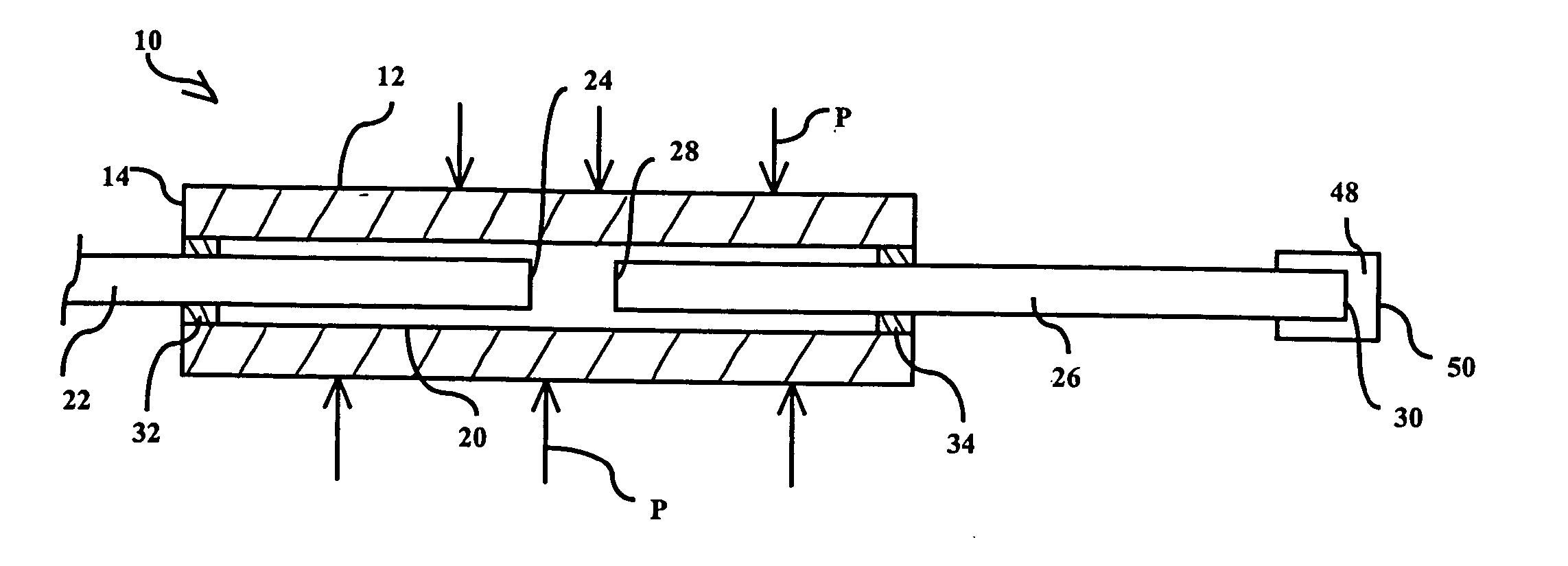
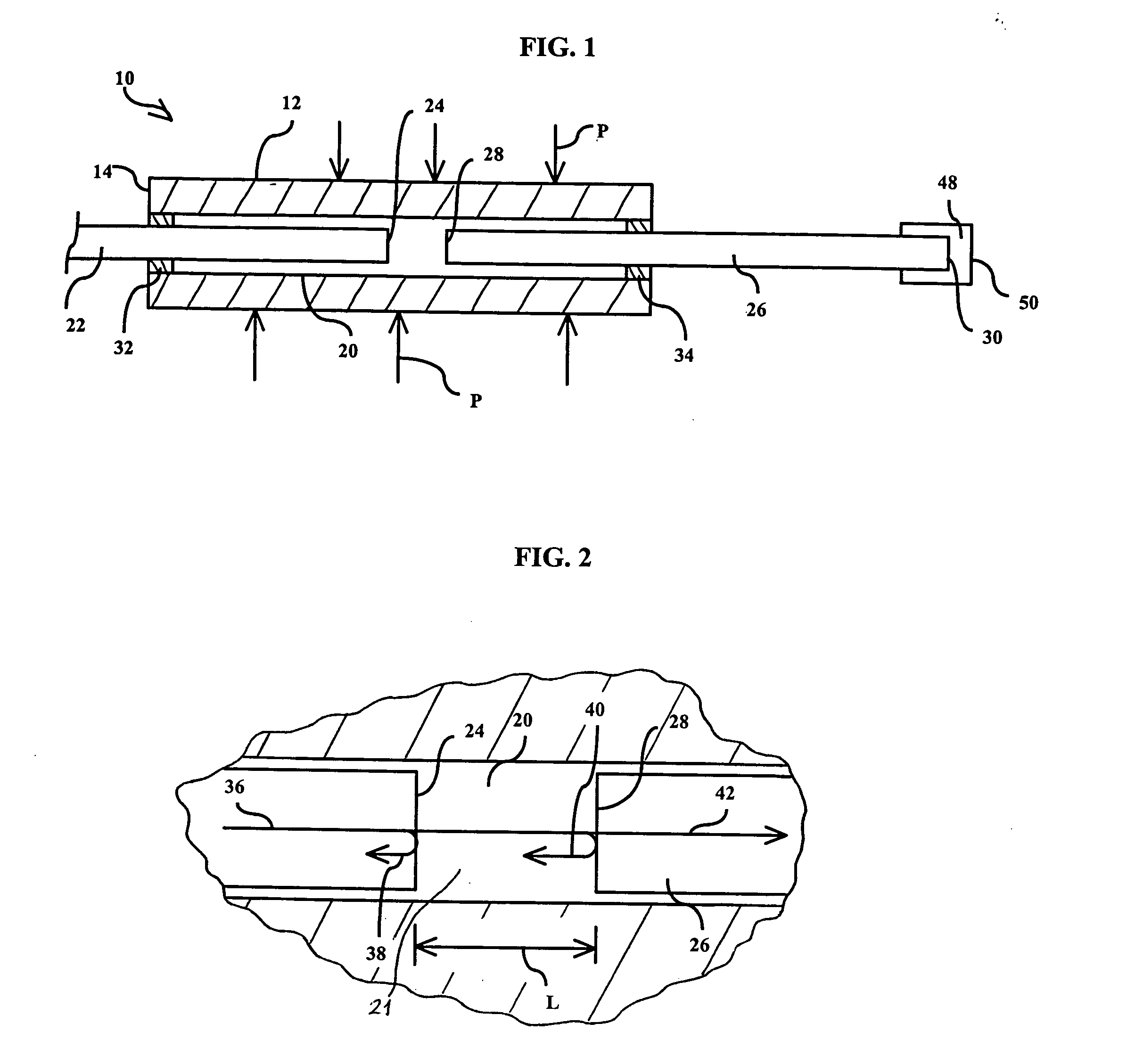
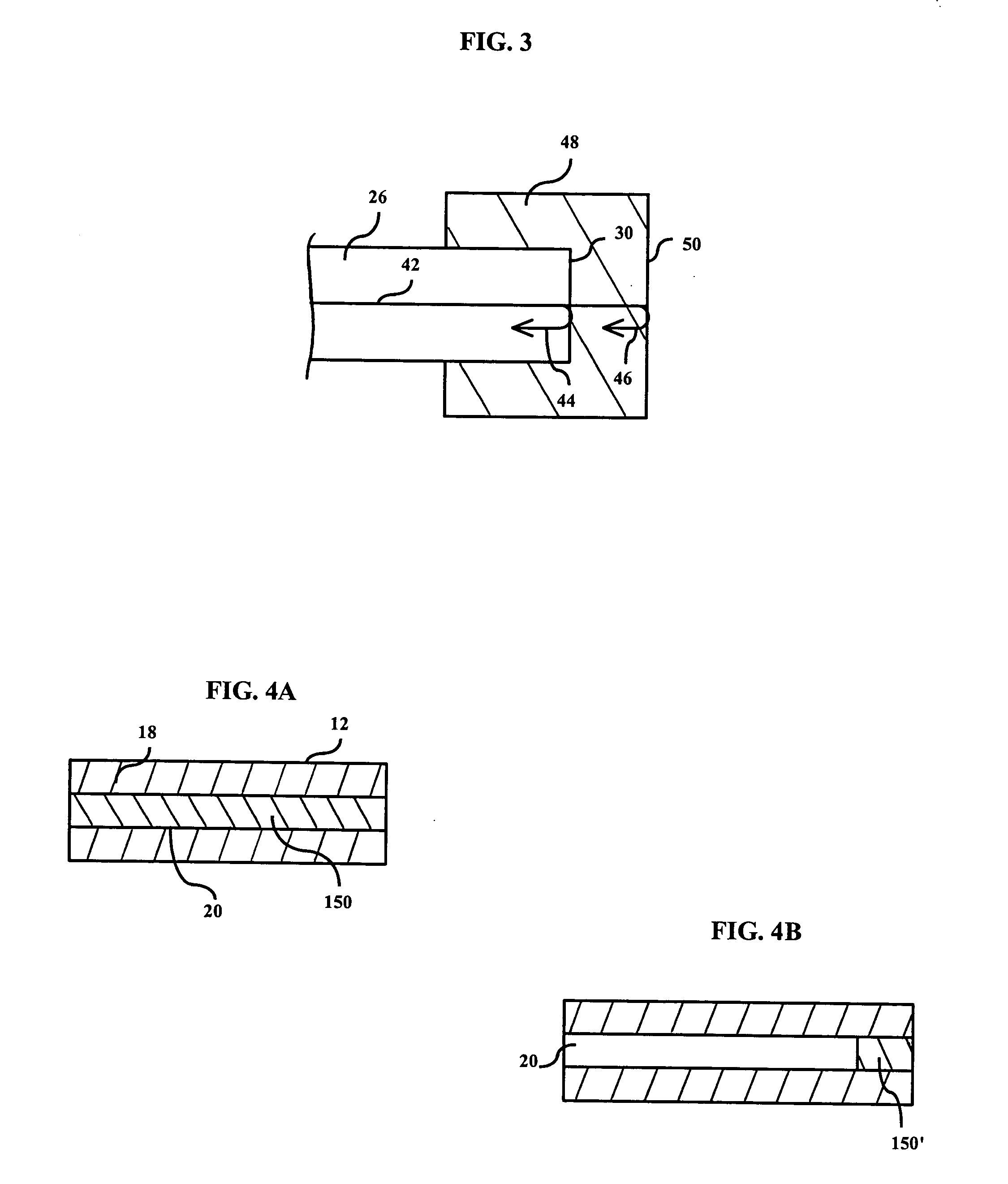
[0026] With reference to FIGS. 1-3, an optical sensor 10 is shown. The sensor 10 includes an input or launch fiber 22 and a reflective fiber 26, both captured within a cavity 20 of a tube 12. Specifically, the launch fiber 22 has a first end 24 which is separated from a first end 28 of the reflective fiber 26 by a gap 21 of the cavity 20. The launch fiber 22 may be a single mode, multimode, polarization maintaining, or plastic fiber. The reflective fiber 26 may be a coreless, multimode, polarization maintaining, or plastic fiber.

[0027] Optical coatings 23, 27 may be applied to, respectively, the first end 24 of the launch fiber 22 and the first end 28 of the reflective fiber 26 (FIG. 7). The optical coatings 23, 27 enhance the spectral characteristics so that demodulation of the gap information may be more accurately and more easily accomplished. Suitable materials for the optical coatings 23, 27 include magnesium fluoride, silicon monoxide, zirconium oxide, tantalum oxide, niobium...


PUM


Abstract

An optical sensor that includes multiple filter cavities for the simultaneous, co-located measurement of pressure and a temperature in a single structure. The sensor may include a single launch fiber bonded to a tube a pre-determined distance from a reflective fiber. The end of the reflective fiber not encased within the tube is enclosed within a cap formed of a material that has a refractive index that changes with changing temperature. Alternatively, a material having a refractive index that changes with changing temperature can be inserted into the tube to take the place of the reflective fiber. Multiple launch fibers may be incorporated within a tube.

Description

FIELD OF THE INVENTION [0001] The invention generally relates to optical sensors, and more particularly to fiber optic systems having three reflective surfaces and two indexes of refraction in between. BACKGROUND [0002] Optical fibers have become the communication medium of choice for long distance communicating due to their excellent light transmission characteristics over long distances and the ability to fabricate such fibers in lengths of many kilometers. Sometimes, the information being communicated is video or audio, while other times the information being communicated is data. [0003] In the petroleum industry, it is important to obtain accurate pressure information during, for example, the drilling of an oil well. For instance, while drilling the drill bit may drill into a high pressure layer, and from at least a safety and environmental standpoint it is important to obtain accurate pressure information. Optical fibers are beginning to be used to communicate pressure informat...

Claims


Application Information

Patent Timeline
IPC IPC(8): G01D5/353G01K11/32G01L11/02G01L19/00
CPCG01K11/3206G01D5/35312G01L19/0092G01L11/025
Inventor ZERWEKH, PAUL S.BOYD, CLARK D.CHILDERS, BROOKSBLEVINS, DANIEL C.
Owner BAKER HUGHES INC
Why Eureka
Try Eureka