Printing and quilting method and apparatus

a printing and quilting technology, applied in the field of quilting, can solve the problems of affecting the quality of quilting around the pre-applied patterns or the quilting of pattern details of a and is difficult to achieve the high quality outline quilting around the pre-applied patterns or the fraction of an inch in scale quilting, and achieves the effect of efficient and economical operation

Inactive Publication Date: 2005-03-10
L & P PROPERTY MANAGEMENT CO
View PDF38 Cites 12 Cited by
  • Summary
  • Abstract
  • Description
  • Claims
  • Application Information

AI Technical Summary

Benefits of technology

[0018] An objective of the present invention is to provide quilt manufacturers, particularly mattress cover manufacturers, with the ability to produce quilted products having a wide variety of patterns that include both quilting and printed or other images or designs efficiently and economically. A particular objective of the invention is to provide such ability without the need to inventory material in a large number of different pre-applied designs.
[0019] A further objective of the invention is to provide for the intricate outline or other coordinated quilting of designs or patterns on multi-layered materials in a highly efficient, economical, high speed and automated manner, particularly by both applying the printed design or pattern and quilting the outline or other coordinated quilted enhancement of the printed design or pattern in sequence on the same manufacturing line.
[0020] Another objective of the present invention is to efficiently provide for customizable printed and quilted patterns on mattress covers, bedspreads and the like, which can be varied on an individual piece basis or with items produced in small quantities. It is a particular objective of the present invention to provide flexibility in the production of mattress ticking and quilted mattress covers having patterns that can differ from product to product.

Problems solved by technology

With such systems, border quilting or coarse pattern quilting can be achieved but high quality outline quilting around the pre-applied patterns or the quilting of pattern details of a fraction of an inch in scale are difficult to achieve, particularly automatically.
With such multi-needle machines, the combining of quilting with pre-applied printed or woven patterns in the fabric which would require registration of the quilting with the pre-applied patterns is usually not attempted.
The cost of such an inventory as well as the storage and handling of such an inventory contributes substantially to the manufacturing cost of bedding products.
With such high-end products, the combining of quilting with pre-applied printed or woven patterns in the fabric may call for registration of the quilting with the pre-applied patterns, which is difficult to achieve with multi-needle machines.
Proposed automated systems using vision systems to follow a preprinted pattern or other schemes to automatically stitch on the preprinted material have been proposed but have not proven successful.
Registration of pattern stitching with preprinted patterns has been a problem.
Correction for misalignment of quilted and printed patterns by repositioning of a quilting or printing head is inadequate if multi-needle quilters are to be used, particularly where angular mis-orientation is present.
Application of registration techniques to roll fed materials, where printing and quilting are performed on the material webs, presents additional problems.
Registration errors that are minor where patterns are applied to individual panels produce cumulative errors when patterns are applied to webs.
This is particularly true where angular orientation errors result due to skewing of the web as it is fed into the subsequent pattern applying machine after removed from a machine in which the first pattern has been applied.
With off-line processes for applying one pattern and then another in registration with the first, one by printing and one by quilting, production of quilts in small batches of pattern combinations is particularly a problem.
As a result, the matching of the second pattern to be applied with the correct pre-applied pattern as the partially completed products are moved from a first machine or production line to a second is critical and a potential source of error as well as production delay.
Frequently, small quantities of each of the variety of products must be made to supply their customers' requirements, requiring the maintenance of inventories of a large number of different patterns of ticking material, which involves substantial cost.
Further, the need to constantly match patterns as well as to change ticking supply rolls when manufacturing such a variety of products in small quantities can be a major factor in reducing the throughput of a mattress making process and delaying production.
These and related problems continually exist in the manufacture of bedspreads, comforters and other quilted products where a variety of products in small quantities is desired.
However, frequent changing of the ticking material to produce products having a variety of appearances, requires interruption of the operation of the quilting machine for manual replacement and splicing of the material.
This adds to labor costs and lowers equipment productivity.
Further, the spliced area of the material web which must be cut from the quilted material is wasted.
Coordination of the two production lines, as well as the matching of border panels with the top and bottom panels, requires well executed control procedures and can lead to assembly errors or production delays.

Method used


Image

  • Printing and quilting method and apparatus
  • Printing and quilting method and apparatus
  • Printing and quilting method and apparatus

Examples


embodiment 100

[0078]FIG. 2 illustrates an embodiment 100 of the invention that employs a single-needle, frame-supported, discrete-panel quilting machine such as those described in U.S. Pat. No. 5,832,849. Other machines of that type are disclosed in U.S. Pat. Nos. 5,640,916 and 5,685,250. These single needle quilting machines apply patterns to panels 129 that are often precut. Such machines are useful for manufacturing comforters, for example. The machine 100 has an operator accessible stack 116 of preformed panels from which the panel 129 is taken and loaded into the machine 100. A conveyor or conveyor system 120 moves a set of panel supporting edge clamps or other edge securements 121 to bring the panel 129 into a fixed position for application of a combination pattern by printing onto the outer top layer 115 of the multilayered fabric 129 and by quilting the multilayered fabric 129.

[0079] In the embodiment 100, a printing station 125, which in this embodiment includes a combined drying station...

embodiment 200

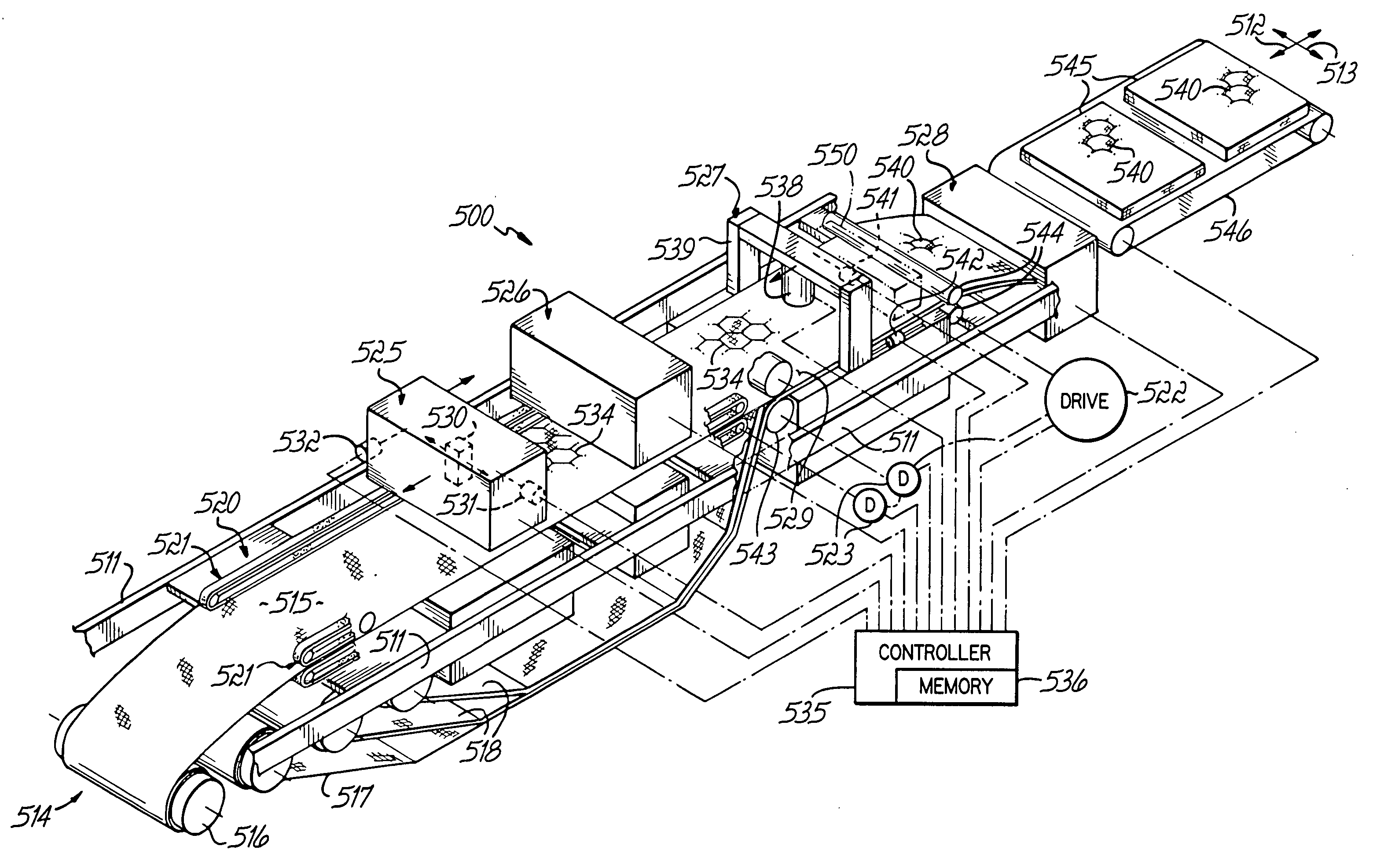
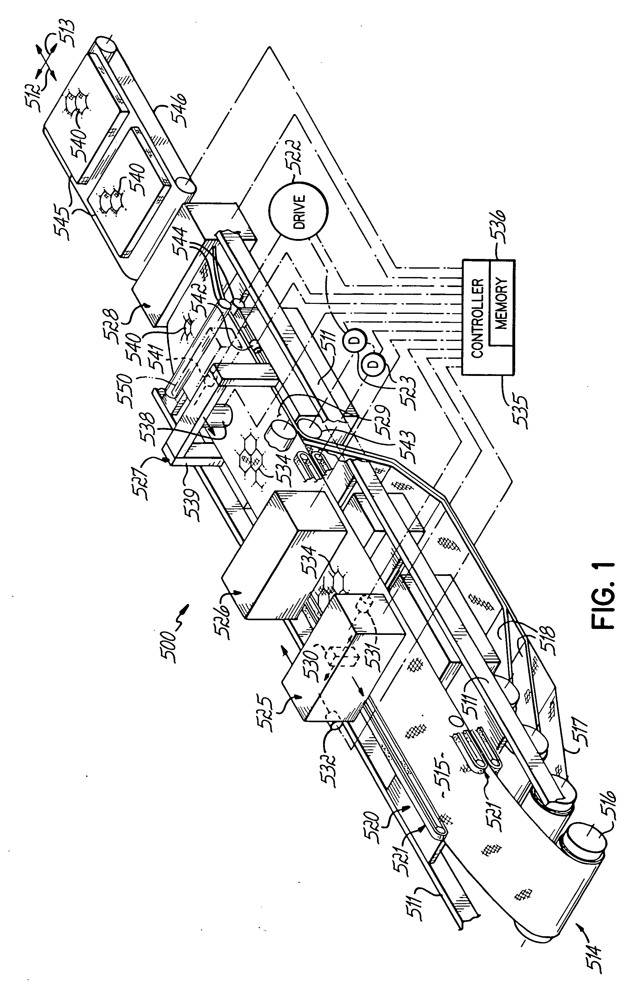
[0082]FIG. 3 illustrates an embodiment 200 that is similar in certain respects to the machine 500 of FIG. 1, but which further includes the capability to apply combination patterns to different areas of ticking material 215 on a wide multilayered fabric 229 to produce top or bottom panels 251 with matching or otherwise corresponding border panels 252 of a mattress cover. In the preferred arrangement, a web of ticking or facing material 215 from a roll 216 is printed in an efficient arrangement of panels on the facing material 215. The machine 200 is provided with a supply 217 of backing material and supplies 218 and 219 of filler material, which are preferably, for this embodiment, of different thicknesses at different positions across the width of the facing material 215, to form the multi-layered fabric 229, on which the arrangement of panels is then quilted at a quilting station 227 in a way that spatially corresponds to the printed patterns. The machine 200 is also provided with...

embodiment 400

[0100] An alternative configuration of the embodiment 400 of FIG. 5 employs magnetic particle brakes for the controllable elements 461 in place of servo motors. With such brakes, differential tension is applied on the opposite side edges of the web 429 as the web is pulled by drive rolls 420 upstream of the quilting station 427. The unequal tension on the opposite side edges of the web 429 affects the skew adjustment. Further, by locating the split feed roll 460 upstream of a set of rolls (not shown) at which the backing and fill layer webs 417 and 418 are joined to the facing web 429, shrinkage of the facing layer 429 bearing the printed pattern can be controlled and limited, so that the printed pattern can be, in effect, lengthened relative to quilted pattern. Typically, the longitudinal scale of the printed pattern at the printing station 425 takes into account predicted shrinkage due to the gathering of material during quilting. Sometimes dimensional changes occur that result in...


PUM


Abstract

A quilting machine (10, 100, 200, 300, 400, 500, 600) is provided with a printing station (20, 125, 225, 325, 425, 525, 611, 626, 631) and a quilting station (44, 127, 227, 327, 427, 527, 627, 632), either on the same or a different production line. Ticking is preprinted with a plurality of different patterns, organized and coordinated by the computer so that a print head can scan the material and print different patterns of different panels (32). Identifying data (40) for matching the panels of a mattress product can be provided in data files and codes can be printed on the fabric. Panels can be matched and assembled into products based on the codes, and quilting, cutting, slitting and other operations can be controlled by printed codes and other data. The quilting and combining of the panels for assembly of a mattress product can be carried out manually or automatically using the data.

Description

[0001] This application is a Continuation of Ser. No. 10 / 185,324, filed Jun. 27, 2002, which is a continuation of Ser. No. 09 / 822,794, filed Mar. 30, 2001, now U.S. Pat. No. 6,435,177, which is a Continuation-in-Part of Ser. No. 09 / 649,471, filed Aug. 28, 2000, now U.S. Pat. No. 6,263,816, each hereby expressly incorporated herein by reference, and to which priority is claimed. [0002] This application is also related to Ser. No. 09 / 480,094, filed Jan. 10, 2000, now U.S. Pat. No. 6,158,366, of which Ser. No. 09 / 649,471 is a Continuation-in-Part, and which is a Continuation-In-Part of Ser. No. 09 / 250,352, filed Feb. 16, 1999, now U.S. Pat. No. 6,012,403, which is a Continuation-In-Part of U.S. patent application Ser. No. 09 / 070,948, filed May 1, 1998, now U.S. Pat. No. 5,873,315, all of which are hereby expressly incorporated by reference herein.FIELD OF THE INVENTION [0003] The present invention relates to quilting, and particularly to the quilting of pattern bearing products such as...

Claims


Application Information

Patent Timeline
Patent Type & Authority Applications(United States)
IPC IPC(8): B41J2/01B41J11/00D04D7/02D05B11/00D05B33/00D06B11/00
CPCB41J2/01B41J3/4078B41J11/002B41J15/04D06B11/0059D05B33/00D05D2305/12D05D2305/22D05B11/00B41J11/00214
Inventor CODOS, RICHARD N.WHITE, M. BURL
Owner L & P PROPERTY MANAGEMENT CO
Why Eureka
Try Eureka