

Double-pipe heat exchanger
- Summary
- Abstract
- Description
- Claims
- Application Information
AI Technical Summary
Benefits of technology
Problems solved by technology
Method used
Image

Examples
first embodiment
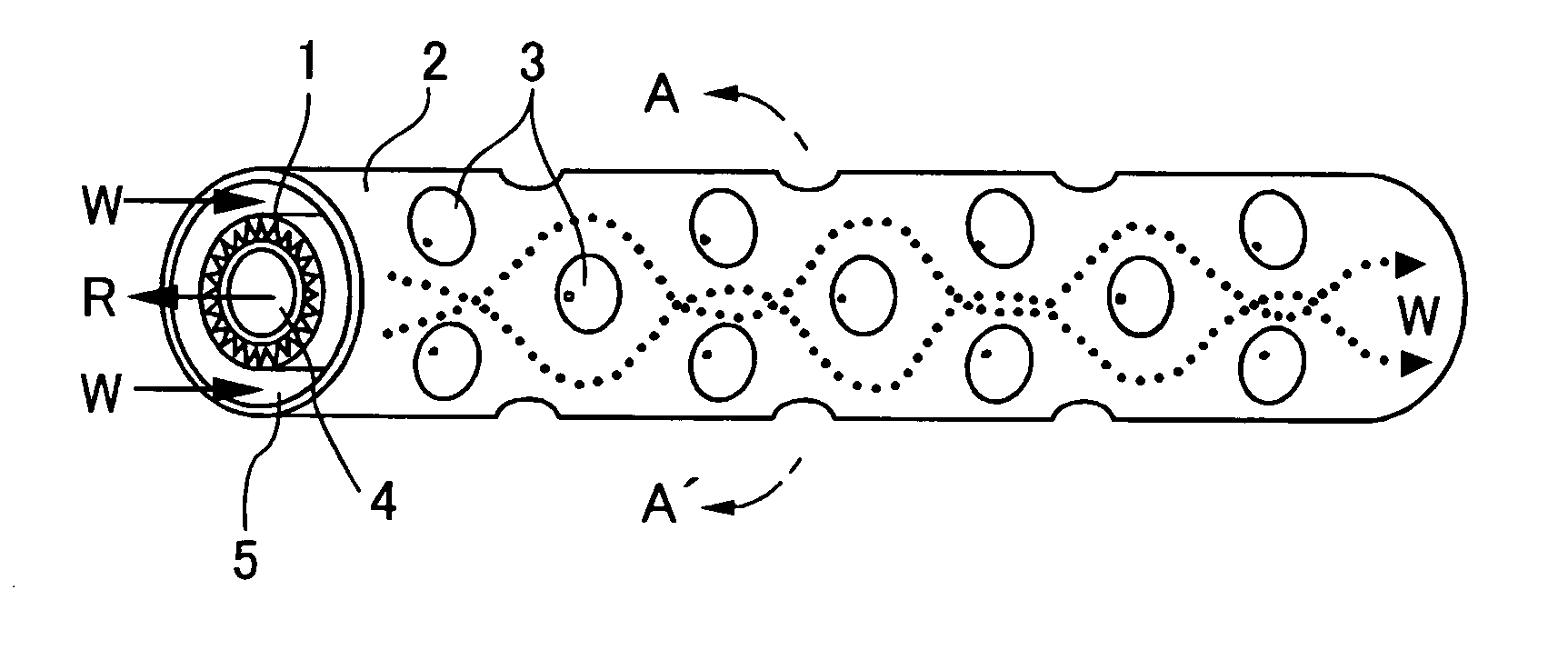
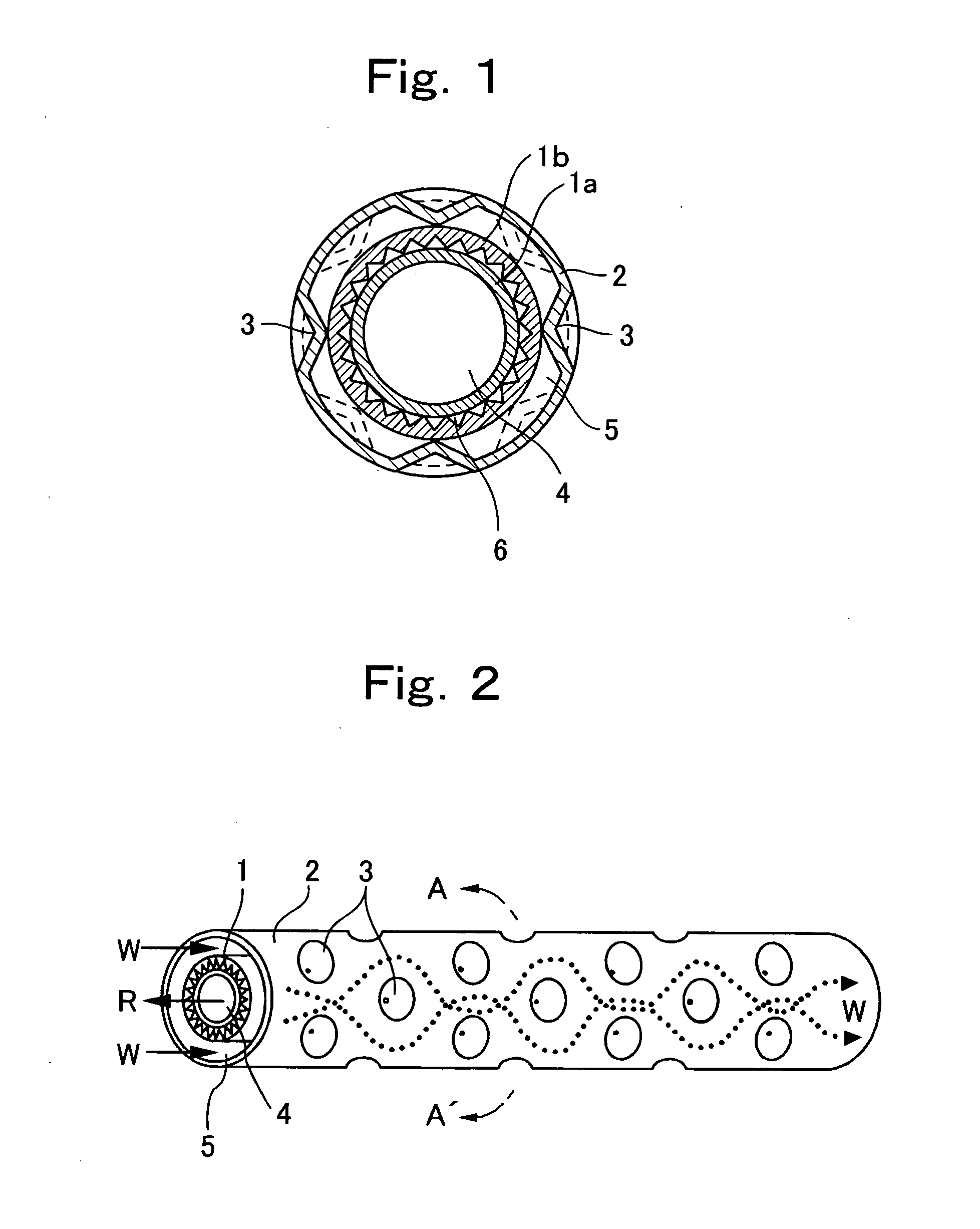
[0040]FIG. 1 is sectional view of a double-pipe heat exchanger and FIG. 2 is a view of a structure of an essential portion of the double-pipe heat exchanger, according to the invention.
[0041] The double-pipe heat exchanger of this embodiment is used as a water refrigerant heat exchanger for warm water in a water heater using carbon dioxide as refrigerant. As shown in FIGS. 1 and 2, an inner pipe 1 is concentrically inserted into an outer pipe 2. FIG. 2 is a sectional view of the double-pipe heat exchanger taken along a line A-A′ in FIG. 1.
[0042] In this embodiment, a refrigerant passage 4 through which refrigerant R flows is formed in the inner pipe 1. A water passage 5 through which water W flows is formed between the inner pipe 1 and the outer pipe 2. The refrigerant R and the water W flow in opposite directions from each other.
[0043] The outer pipe 2 has a plurality of substantially conical projections 3. The projections 3 are formed by denting the outer pipe 2 from its outside...
second embodiment
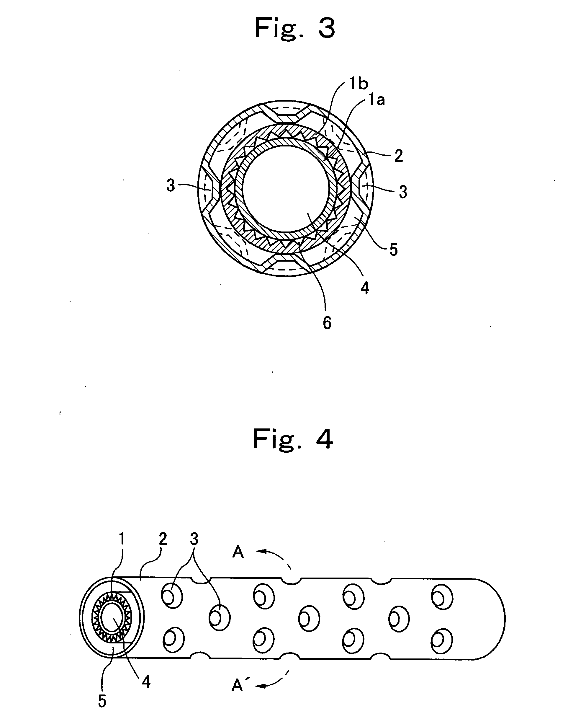
[0052]FIG. 7 shows a structure of an essential portion of a double-pipe heat exchanger according to the invention.
[0053] The plurality of projections 3 of the outer pipe 2 are disposed such as to helically surround the inner pipe 1. Thus, fluid (water W) between the inner pipe 1 and the outer pipe 2 flows helically, the flow velocity of the fluid (water W) is increased, the turbulent flow is facilitated, and the heat transfer performance is further facilitated.
third embodiment
[0054] FIGS. 8 to 10 show a double-pipe heat exchanger according to the invention.
[0055]FIG. 9 shows a cross section (A-A′) of the double-pipe heat exchanger closer to a water entrance. FIG. 10 shows a cross section (B-B′) of the double-pipe heat exchanger closer to a water exit.
[0056] The number of projections 3 per unit length in the water entrance area is smaller than that in the water exit area. As shown in FIGS. 9 and 10, depth of the projections 3 disposed in the water entrance area is shallower than that in the water exit area. With this structure, the passage between the inner pipe 1 and the outer pipe 2 closer to the water exit through which high temperature water flows can be secured widely, and it is possible to avoid clogging of the water passage which may be caused by scale such as calcium carbonate deposited by high temperature water. When a distance between the inner pipe 1 and the outer pipe 2 is originally small, the closing of the water passage due to scale or the...
PUM
 Abstract
Description
Claims
Application Information