

Wiper plug with packer
- Summary
- Abstract
- Description
- Claims
- Application Information
AI Technical Summary
Benefits of technology
Problems solved by technology
Method used
Image

Examples
Embodiment Construction
[0039] The Self-Retaining Wiper Plug
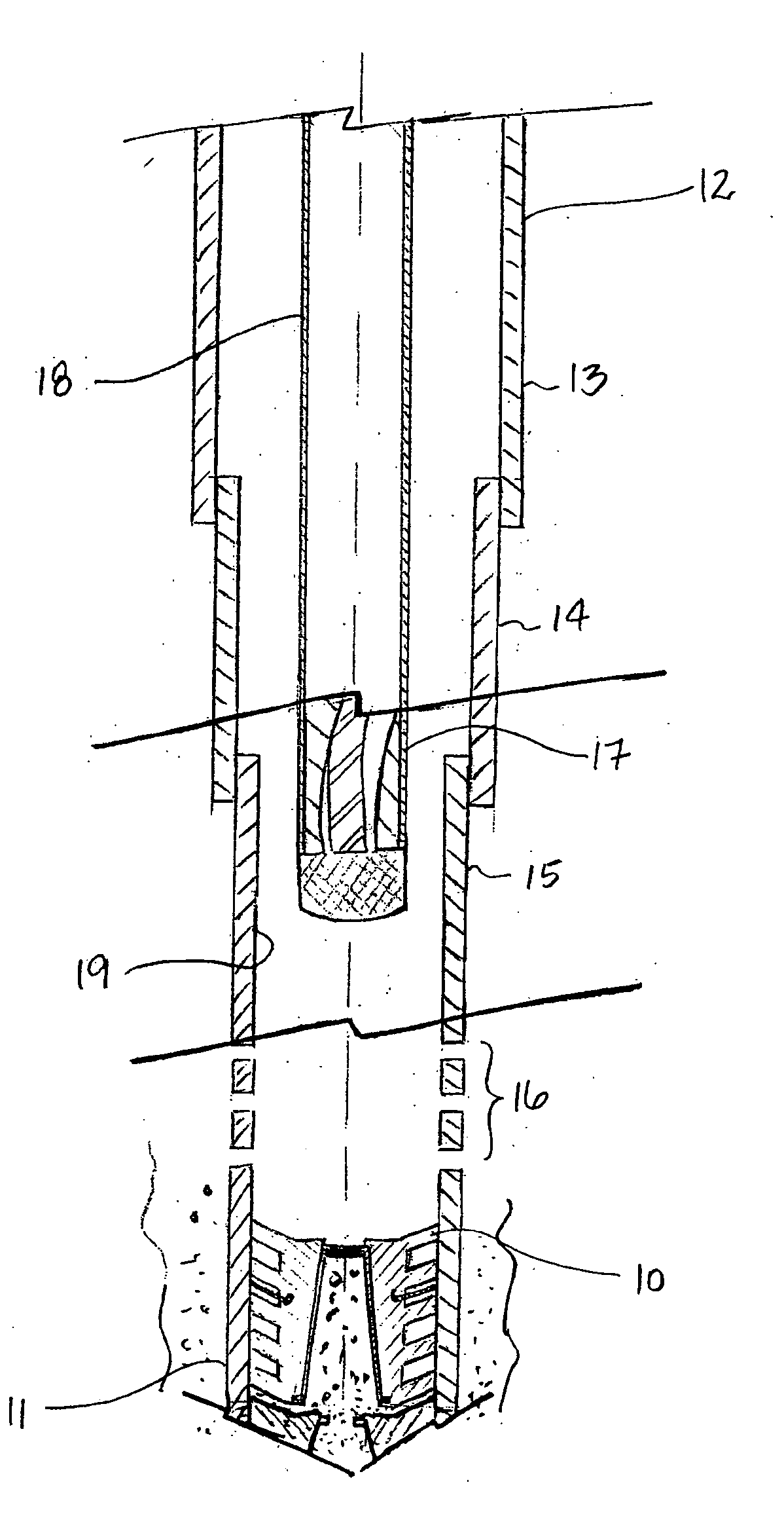
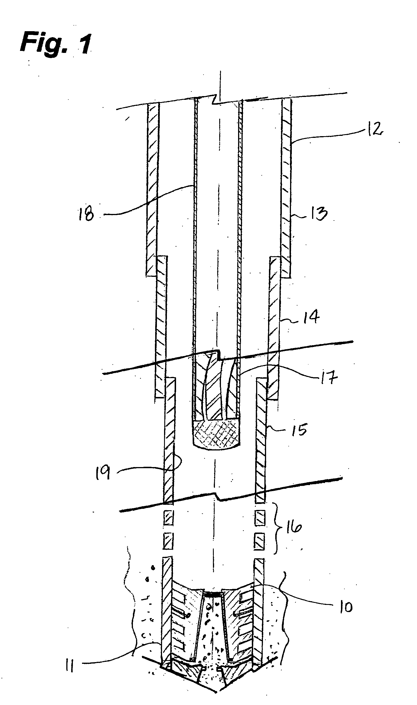
[0040] Having reference to FIG. 1, a cementing plug 10 is shown positioned adjacent a bottom 11 of a casing string 12 comprising, in order beginning from surface (not shown): surface casing 13, intermediate casing 14 and production casing 15. The cementing plug 10 is located below a plurality of perforations 16 in the production casing 15 and below a pump 17 lowered into the casing 12 at the end of a production string 18.
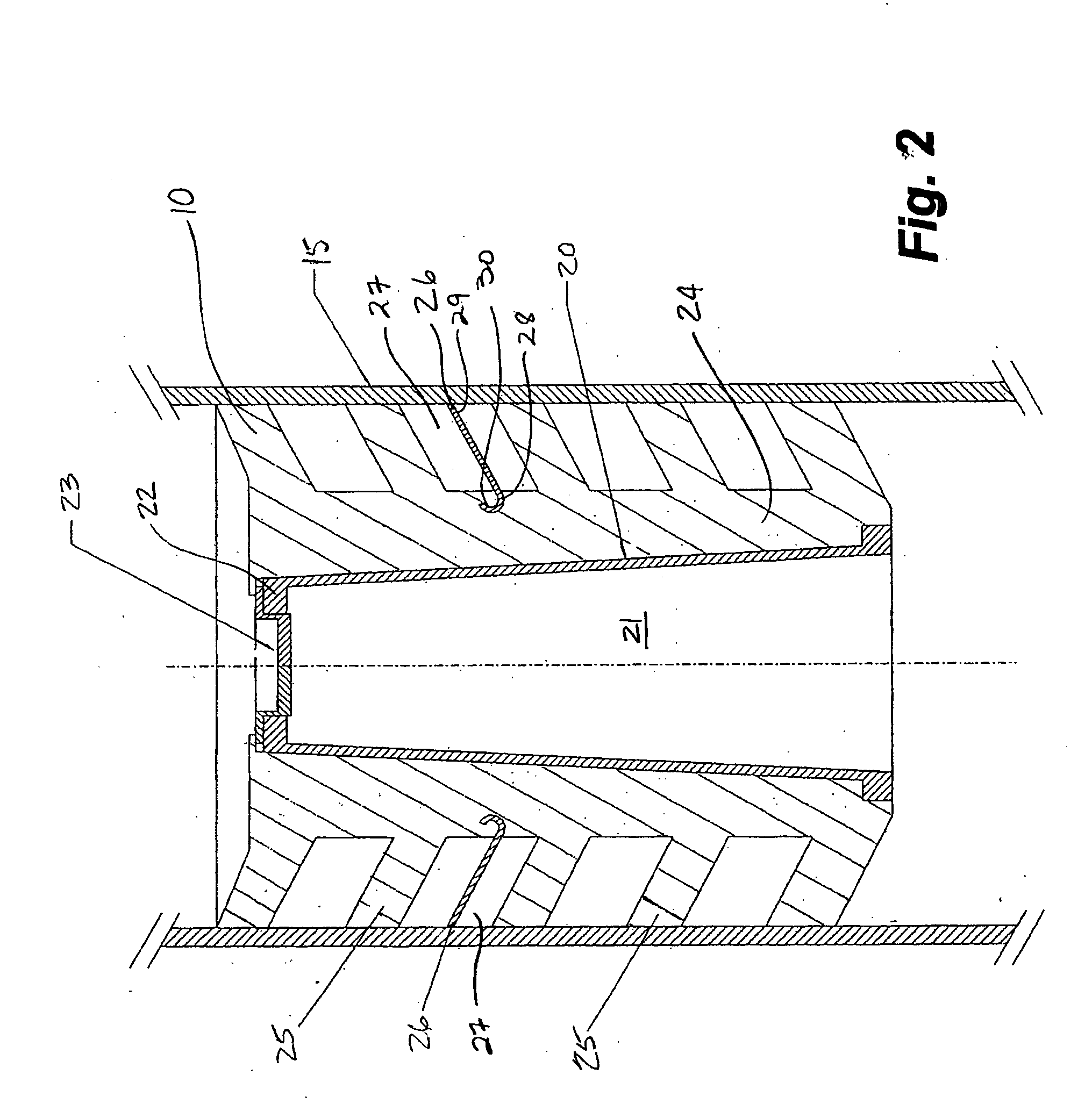
[0041] As shown in FIG. 2, and in a preferred embodiment of the invention, the cementing plug 10 comprises a core 20. The core 20 is covered with an elastomeric covering 24 having a plurality of wipers 25 formed thereon. Preferably, the core 20 defines a bore 21 therethrough. A top end 22 of the core 20 is fitted with a rupture element 23 to permit the passage of cement slurry during cementing should the plug 10 be used inadvertently as a bottom wiper plug. Typically, the rupture element 23 is designed to rupture only at a prede...
PUM
 Abstract
Description
Claims
Application Information