Laser machine tool with image sensor for registration of workhead guidance system

a technology of workhead guidance and laser machine tools, which is applied in the field of laser equipped machine tools, can solve the problems of not being able to ensure the registration of the workhead guidance system relative to the workpiece, the motion of the laser machine tool is not perfectly straight, and the known methods of locating parts on the laser machine tool are not entirely satisfactory in addressing this registration problem. , to achieve the effect of keeping the image sensor lens clean

Inactive Publication Date: 2005-03-10
W A WHITNEY
View PDF5 Cites 47 Cited by
  • Summary
  • Abstract
  • Description
  • Claims
  • Application Information

AI Technical Summary

Benefits of technology

[0013] Other objectives of the present invention are to provide a method to automatically calibrate an image sensor mounted on a laser machine tool, to automatically focus an image sensor moun

Problems solved by technology

The work support carrying and guidance system is such that the position of the work support is repeatable but its motion is not perfectly straight.
Locating pins locate the work support, also called a worktable or a pallet, final position but the locating pins cannot assure that registration of the workhead guidance system relative to the workpiece is maintained.
Known methods of locating a part on a laser machine tool are not entirely satisfactory in addressing this registration problem.
Laser workhead nozzle capacitive sens

Method used


Image

  • Laser machine tool with image sensor for registration of workhead guidance system
  • Laser machine tool with image sensor for registration of workhead guidance system
  • Laser machine tool with image sensor for registration of workhead guidance system

Examples


Embodiment Construction

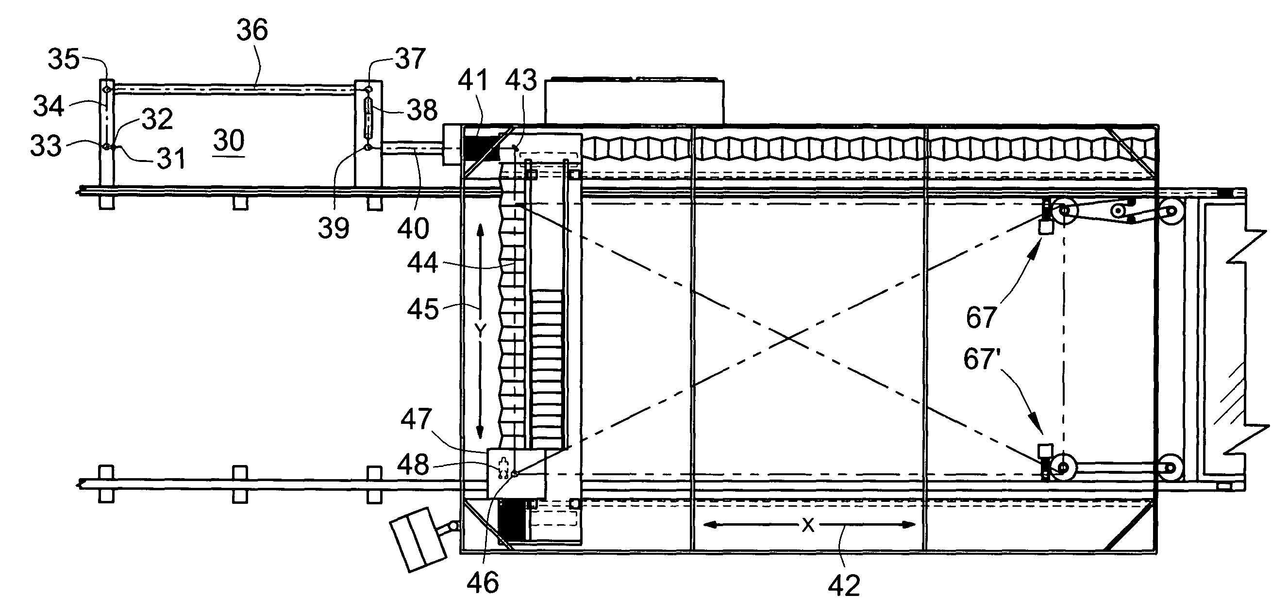
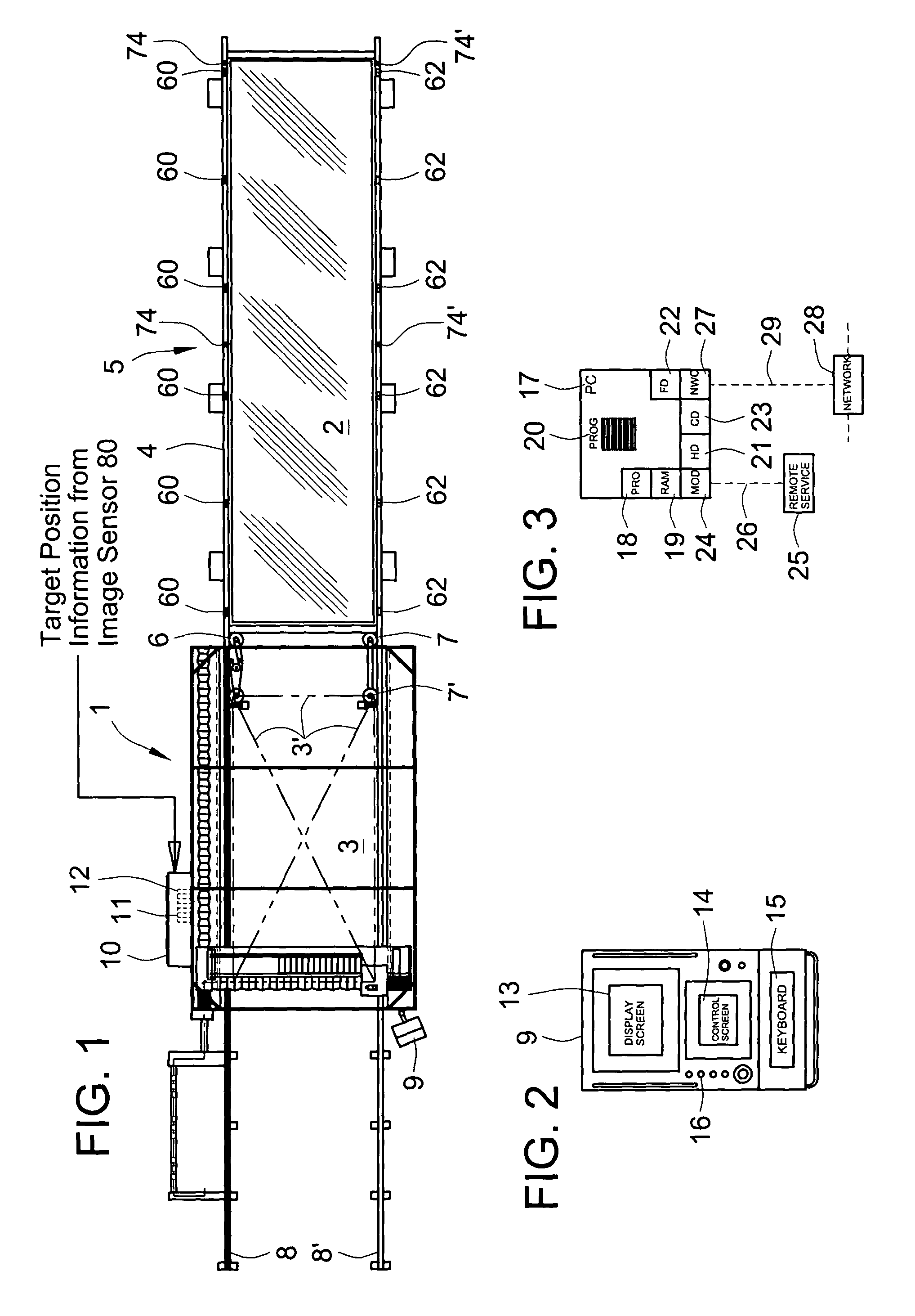
[0045]FIG. 1 is an illustration of a computer controlled laser machine tool 1 wherein a workpiece 2 is larger than a work zone 3 of the machine tool. The work zone 3 of exemplar machine tool 1 is nominally ten feet wide by 20 feet six inches long and the workpiece 2 is nominally ten feet wide by forty feet long. The work zone 3 is outlined and crossed by phantom lines 3′. The workpiece 2 is laying on a translatable work support 4. The translatable work support 4 is also called a worktable or a pallet. The worktable 4 is residing on a load / unload station 5 and is driven in and out of the machine tool work zone by a friction drive apparatus 6. A pair of wheels 7 and 7′ counteracts the driving forces of friction drive 6 such that the worktable 4 remains on its guide way. Support rails 8 and 8′ support the leading end of worktable 4 when it extends beyond the work zone 3. Operator Station 9 is the man machine interface for the machine tool 1. Electrical cabinet 10 houses a computer nume...


PUM

PropertyMeasurementUnit
Sizeaaaaaaaaaa
Distanceaaaaaaaaaa
Erroraaaaaaaaaa

Abstract

A computer controlled laser machine tool is provided wherein the machine tool work zone is smaller than the size of the workpiece that can be processed. The machine tool has an apparatus to register the workhead guidance system to the workpiece without requiring a hole in the workpiece. The machine tool is adapted with an image sensor, a form of a digital camera, to measure the position of targets etched in or affixed to the surface of the workpiece. Registration of the workhead guidance system relative to the workpiece is checked before and after the workpiece support is indexed.

Description

FIELD OF THE INVENTION [0001] The present invention relates generally to machine tools and more particularly relates to laser equipped machine tools for cutting, welding or marking a workpiece. The present invention specifically relates to computer controlled laser machine tools for cutting, marking, or welding a workpiece wherein the machine tool work zone is smaller than the workpiece such that the workpiece is indexed through the work zone for processing. BACKGROUND OF THE INVENTION [0002] A computer controlled machine tool has been developed for laser cutting and marking a workpiece wherein the working zone of the machine tool is smaller than the workpiece that can be processed. The workpiece is carried on a translatable worktable or pallet that is indexed through a working zone. There is a small overlap within the work zone at the trailing edge of the first working position and at the leading and trailing edge of subsequent working positions. The leading portion of the workpiec...

Claims


Application Information

Patent Timeline
IPC IPC(8): B23K26/04
CPCB23K26/043B23K26/04
Inventor LEGGE, JOHN C.BERRY, JIMMY D.FARRIS, ROBERT J.
Owner W A WHITNEY
Why Eureka
Try Eureka