Double-sided liquid crystal display device

Active Publication Date: 2005-03-10
BOE TECH GRP CO LTD
View PDF8 Cites 18 Cited by
  • Summary
  • Abstract
  • Description
  • Claims
  • Application Information

AI Technical Summary

Benefits of technology

[0015] Furthermore, according to an exemplary aspect of the present invention, the double-sided light source assembly includes a transparent substrate and electroluminescent elements functioning as the light-emitting-region changing device. The electroluminescent elements are provided in different light-emitting regions on the transparent substrate and are capable of emitting light from both sides of the elements. Moreover, the switching device turns on the electroluminescent elements corresponding to the position and dimensions of one of the liquid crystal display panels in synchronization with the display timing of the corresponding liquid crystal display panel. Accordingly, since the double-sided light source assembly includes the transparent substrate and the electroluminescent elements which function as the light-emitting-region changing device and are provided in different light-emitting regions on the transparent substrate, and the switching device turns on the electroluminescent elements corresponding to the position and dimensions of one of the liquid crystal display panels in synchronization with the display timing of the corresponding liquid crystal display panel, a low power consumption can be achieved. Moreover, this permits multiple options for the color of the backlight as well as flexibility in the shape of the light-emitting regions.
[0016] Furthermore, according to an exemplary aspect of the present invention, when the liquid crystal display panels are respectively disposed on the inner surface and the outer surface of a cover which can be opened or closed, the switching device performs control of the light-emitting-region changing device in response to the opening/closing sta

Problems solved by technology

According to such double-sided liquid crystal display devices, however, since two liquid crystal display units each having a liquid crystal display panel with a backlight are disposed adjacent to each other in a back-to-back manner, the overall thickness tends to become large and spoil the portability of such information terminals.
Moreover, due to the trend of reduced thickness in recent years, a sufficient angle of inclination for the wedge-shaped light-guiding plates cannot be obtained.
Conseq

Method used


Image

  • Double-sided liquid crystal display device
  • Double-sided liquid crystal display device
  • Double-sided liquid crystal display device

Examples


first exemplary embodiment

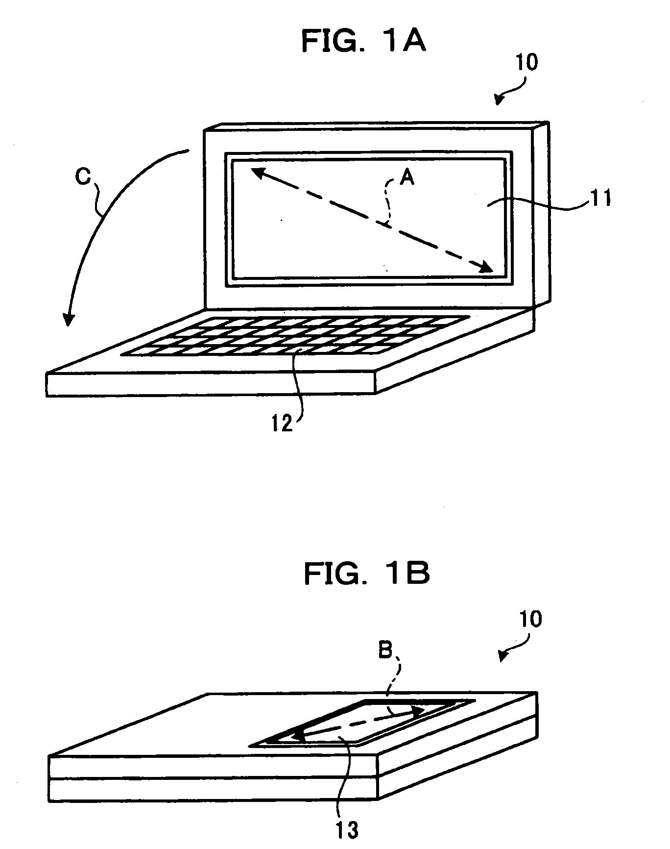
[0030]FIGS. 1A and 1B are schematics of a foldable PDA (Personal Digital Assistant) 10 including a double-sided liquid crystal display device of a first exemplary embodiment according to the present invention. FIG. 1A is a schematic showing the PDA 10 in a state where a cover is opened. FIG. 1B is a schematic showing the PDA 10 in a state where the cover is closed. As shown in FIG. 1A, the PDA 10 is provided with a 5-inch main display panel 11 (A=5 inches) on the inner surface of the cover, and a main body 12 which is combined with the cover by a hinge in a foldable manner and which includes, for example, a keyboard, a controller, a processor, and memory. When the cover of the PDA 10 is closed in a direction indicated by an arrow C, as seen from FIG. 1B, the PDA 10 is provided with a 2-inch sub-display panel 13 (B=2 inches) on the outer surface, i.e. the rear surface of the cover.

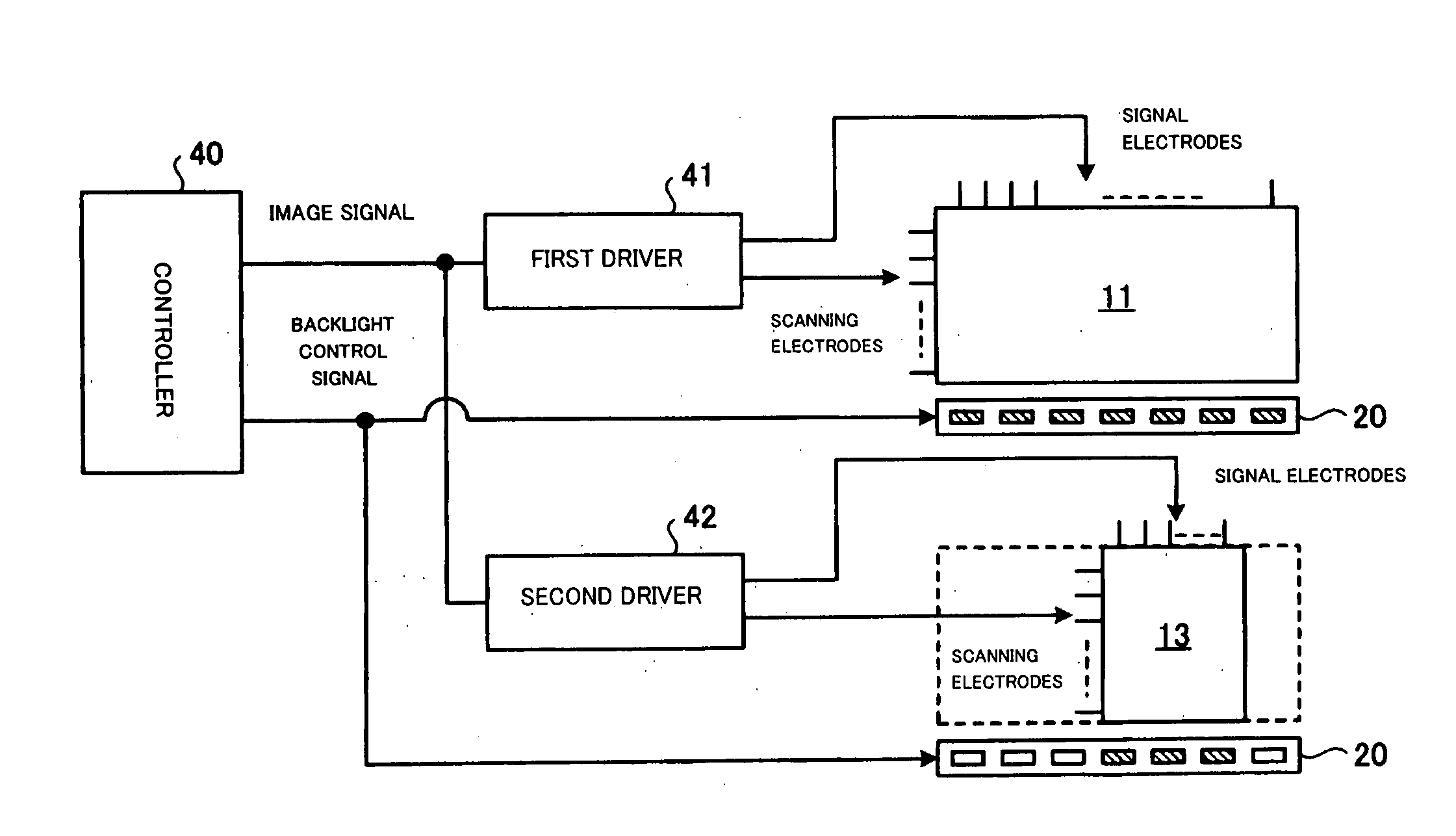
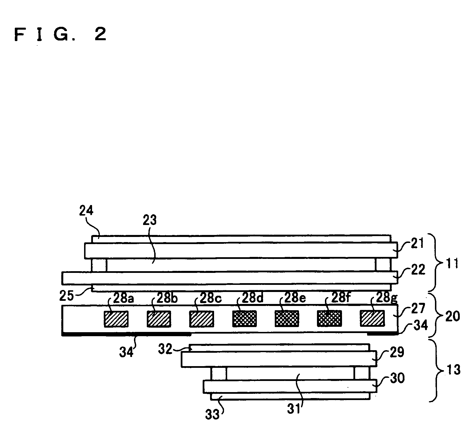
[0031]FIG. 2 is a schematic illustrating the structure of the main display panel 11 and the sub-display...

second exemplary embodiment

[0045]FIG. 7 is a schematic illustrating a main display panel and a sub-display panel according to a second exemplary embodiment. In FIG. 7, components that are similar or corresponding to the components in FIG. 2 are indicated by the same reference numerals, and the description of those components will be omitted. The main feature of the second exemplary embodiment is that the main display panel 11 and the sub-display panel 13 have the same size but are not aligned with each other in a cross-sectional view. Even in this case, the power consumption of the LEDs of the backlight 20 is similarly reduced.

[0046] In related art devices, all six LEDs had to be turned on when the display operation was performed in the main display panel 11 or the sub-display panel 13. However, referring to FIG. 7, according to the second exemplary embodiment, only four LEDs need to be turned on to perform image display in the main display panel 11 or in the sub-display panel 13. This reduces the power cons...

third exemplary embodiment

[0048]FIG. 8 is a schematic illustrating a main display panel and a sub-display panel according to a third exemplary embodiment. In FIG. 8, components that are similar or corresponding to the components in FIG. 2 are indicated by the same reference numerals, and the description of those components will be omitted. The main feature of the third exemplary embodiment is that the sub-display panel 13 is larger than the main display panel 11, and the two panels are positioned such that they do not overlap with each other. Also in this case, the power consumption of the LEDs of the backlight 20 is reduced.

[0049] In related art devices, all six LEDs had to be turned on when the display operation was performed in the main display panel 11 or the sub-display panel 13. However, referring to FIG. 8, according to the third exemplary embodiment, only two LEDs need to be turned on for image display by the main display panel 11, reducing the power consumption by about 66%. Moreover, four LEDs nee...


PUM


Abstract

To achieve thinner liquid crystal display panels and to reduce the power consumption for turning on a backlight during an image display operation to a minimum amount, a controller controls display operations of a main display panel and a sub-display panel via a first driver and a second driver. Based on the controlling of the display operations, the controller performs lighting control of LEDs of a backlight corresponding to the dimensions and position of the display panel used for image display. Accordingly, the backlight can be turned on for the display panel used for image display by consuming a minimum amount of power. Furthermore, the backlight includes a light-guiding plate and multiple LEDs and can emit light from both sides of the backlight, thus achieving reduction in thickness.

Description

BACKGROUND OF THE INVENTION [0001] 1. Field of Invention [0002] The present invention relates to double-sided liquid crystal display devices, and particularly, to a double-sided liquid crystal display device which is provided with liquid crystal display panels and a double-sided light source assembly that emits light from two sides thereof to function as a backlight for the display panels. In such a device, each liquid crystal display panel is disposed adjacent to any position at each side of the light source assembly. An image display operation is performed by switching between the display panels. [0003] 2. Description of Related Art [0004] Double-sided liquid crystal display devices have been used in mobile information terminals, such as mobile phones and PDAs (Personal Digital Assistants) that are provided with foldable covers. On the inner and outer surfaces of the cover of such an information terminal, two liquid crystal display units are disposed in a back-to-back manner to fo...

Claims


Application Information

Patent Timeline
IPC IPC(8): F21S2/00G02F1/1347F21S8/04F21Y101/02G02F1/133G02F1/1333G02F1/13357G06F1/16G06F1/32G06F3/14G09F9/00G09F9/35G09F9/40G09G3/20G09G3/34G09G3/36
CPCG02B6/0063Y02B60/1242G02B6/0073G02F1/133615G02F2001/133342G06F1/1616G06F1/1637G06F1/1647G06F1/1677G06F1/3203G06F1/3265G06F3/1423G09G3/342G09G2320/062G09G2330/021G09G2360/04G02B6/0068Y02D10/00G02F1/133342G02F1/133
Inventor SUZUKI, NOBUTAKA
Owner BOE TECH GRP CO LTD
Why Eureka
Try Eureka