Map display device and navigation device

a map display and navigation device technology, applied in navigation instruments, instruments, animations, etc., can solve the problems of increasing the amount of information, not fully using the advantages described above, and difficulty in displaying various types of information on a navigation map image without newly creating object models

Inactive Publication Date: 2005-03-10
SAKAMOTO KIYOMI +3
View PDF69 Cites 72 Cited by
  • Summary
  • Abstract
  • Description
  • Claims
  • Application Information

AI Technical Summary

Benefits of technology

[0026] Therefore, an object of the present invention is to provide a map display device and a navigation device helping a user intuitively understand information without busily moving his / her eyes. Here, the information includes time varying information about regulations, traffic jam, and various information accessible through the Internet, which are all arranged on a map image for display.
[0027] Another object of the present invention is, in the map display device and the navigation device, to reduce the capacity of a storage medium for object model while reducing the amount of incoming information.

Problems solved by technology

This is because object models prepared for map display are unchangeable, and thus color change is the only way left for the conventional navigation device to display such information without newly creating object models.
The issue here is, the conventional navigation device basically displays information displayed on the Internet browser separately from a navigation map image.
Therefore, when the vehicle is in motion, such advantages as described above are not fully used.
For the conventional navigation device, however, displaying various types of information all together on a navigation map image without newly creating object models is quite difficult, except changing the color of roads and other object models.
With such structure, however, the amount of information is consequently increased, and thus this structure is not economically practical.
With such structure, however, a storage medium for object model is required to be large in capacity, resulting in low cost-effectiveness.

Method used


Image

  • Map display device and navigation device
  • Map display device and navigation device
  • Map display device and navigation device

Examples


first embodiment

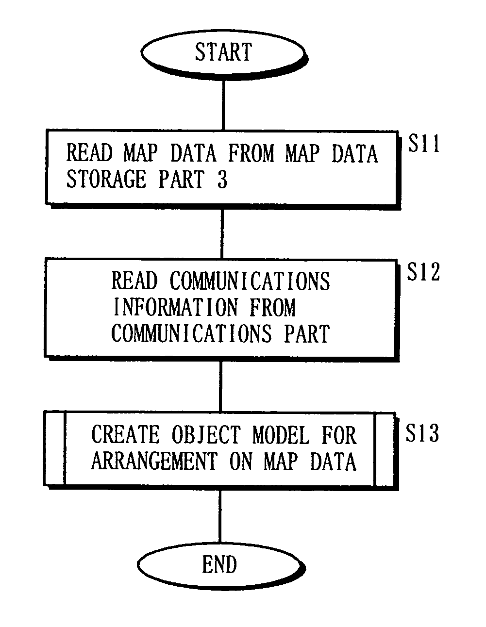
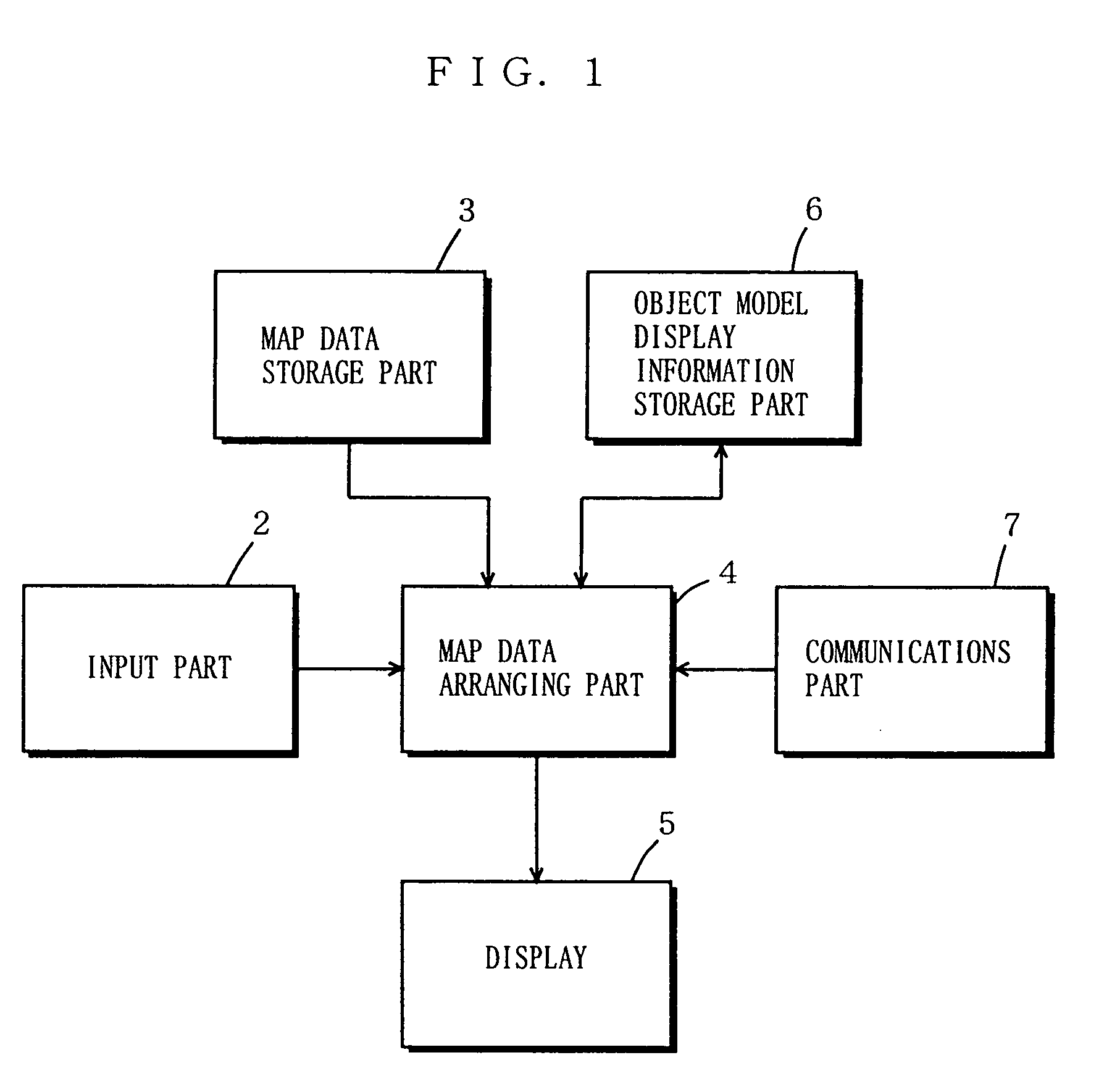
[0135]FIG. 1 is a block diagram showing the structure of a map display device according to a first embodiment of the present invention. In FIG. 1, the map display device includes the input part 2, the map data storage part 3, a map data arranging part 4, the display 5, an object model display information storage part 6, and the communications part 7. Here, any constituent found in FIGS. 66 and 67 is denoted by the same reference numeral.

[0136] The input part 2 is user-operable and composed of a remote controller, touch sensor, keyboard, mouse, and the like. With the input part 2, functional selection and point settings for the map display device (processing item change, map switching, hierarchical level change), for example, are done. Outputted from the input part 2 is instruction information, which is forwarded to the map data arranging part 4.

[0137] The map data storage part 3 is composed of an optical disk (e.g., CD, DVD), hard disk, semiconductor memory card (e.g., SD card), a...

second embodiment

[0249]FIG. 33 is a block diagram showing the structure of a navigation device according to a second embodiment of the present invention. In FIG. 33, the navigation device includes the input part 2, the map data storage part 3, the map data arranging part 4, the display 5, the object model display information storage part 6, the communications part 7, the position detection part 9, a route selection part 10, and a guiding part 11.

[0250] Herein, the input part 2, the map data storage part 3, the map data arranging part 4, the display 5, the object model display information storage part 6, and the communications part 7 operate almost similarly to those in the map display device of FIG. 1. Also, the position detection part 9, the route selection part 10, and the guiding part 11 herein operate similarly to those in the navigation device of FIG. 67.

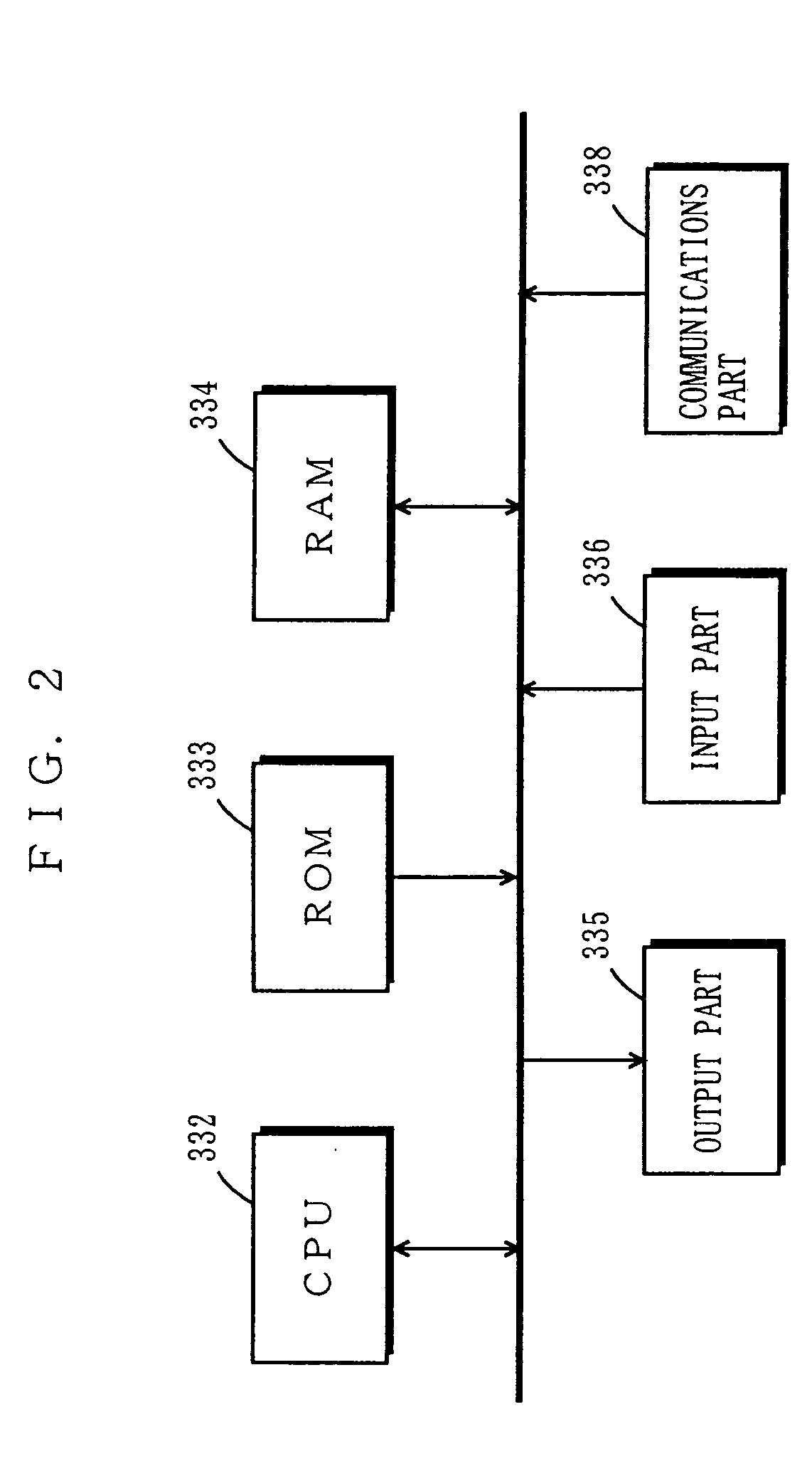
[0251] Such structured navigation device of FIG. 33 can be realized in a general computer system as is the map display device of FIG. 1. The...

third embodiment

[0262]FIG. 36 is a block diagram showing the structure of a map display device of a third embodiment according to the present invention. In FIG. 36, the map display device includes the input part 2, the map data storage part 3, the map data arranging part 4, the display 5, the object model display information storage part 5, the communications part 7, and a time information storage part 8. The map display device of FIG. 36 is additionally provided with the time information storage part 8 compared with the one in FIG. 1. Described next below is the time information storage part 8 about its structure and operation.

[0263] The time information storage part 8 is composed of an optical disk (e.g., CD, DVD), hard disk, semiconductor memory card (e.g., SD card), and the like, and stores time information having time and place interrelated therein. That is, the time information indicates a mobile unit, for example, locating where at what time in a table or equations. Such time information in...


PUM


Abstract

In a map display device, a communications part 7 receives various information from an external system, and a map data arranging part 4 arranges in a map space object models each indicating those various information. Such data arrangement is done based on map data stored in a map data storage part 3, information from the communications part 7 and an input part 2, and object model display information stored in an object model display information storage part 6. A display 5 then displays a resultant map image. In such manner, various time-varying information are appropriately arranged for display on the map image so as to make a user intuitively understand what those information mean.

Description

BACKGROUND OF THE INVENTION [0001] 1. Field of the Invention [0002] The present invention relates to map display devices and navigation devices and, more specifically, to a map display device and a navigation device for analyzing information externally provided through a communications part, and converting the information into applicable object models for display on a map. [0003] 2. Description of the Background Art [0004] In a conventional type of map display device and navigation device, information about traffic and road regulations from any existing information communications system, and information from the Internet are not displayed on a navigation map but on a separately-provided schematic map. That is, such information is not converted into applicable object models for display on the navigation map. [0005] Here, the existing information communications system includes VICS (Vehicle Information and Communication System), wherefrom road information about traffic jam and acciden...

Claims


Application Information

Patent Timeline
Patent Type & Authority Applications(United States)
IPC IPC(8): G01C21/36G09B29/00
CPCG01C21/3638G01C21/3682G09B29/007G01C21/3694G01C21/3685
Inventor SAKAMOTO, KIYOMIHAMADA, HIROYUKIATA, TERUAKIYAMASHITA, ATSUSHI
Owner SAKAMOTO KIYOMI
Why Eureka
Try Eureka