Liquid ejecting apparatus and liquid container holder thereof

a technology of liquid ejecting apparatus and liquid container, which is applied in the direction of printing, etc., can solve the problems of complicated ink cartridge removal operation, complicated mounting operation of ink cartridge on the apparatus body, and ink cartridge itself being enlarged, so as to prevent the ink cartridge from breaking and smooth operation of the rotation lever member

Inactive Publication Date: 2005-03-10
SEIKO EPSON CORP
View PDF0 Cites 70 Cited by
  • Summary
  • Abstract
  • Description
  • Claims
  • Application Information

AI Technical Summary

Benefits of technology

[0083] According to the present invention, a liquid leaking when mounting and demounting a liquid container and a liquid leaking when the liquid container is not mounted can be prevented from diffusion free of complication of the apparatus structure and enlargement of the apparatus.
[0084] According to the present invention, a structure for preventing the electric cable connected to the connector on the translationally movable member side from disconnection can be formed in a limited small space.
[0085] Furthermore, according to the present invention, the electric cable displaced when the translationally movable member moves forward or backward can be prevented from being caught by surrounding members.
[0086] According to the present invention, the smooth operation of the rotation lever member can be ensured without increasing the size of the liquid ejecting apparatus.
[0087] Further, according to the present invention, the fixing of the liquid container in the mounted state can be prevented from releasing by mistake.
[0088] Furthermore, according to the present invention, the stopper pin of the rotation lever member can be prevented from breaking even when the liquid container in the mounted state is unreasonably pulled out by a user.

Problems solved by technology

However, in such a cartridge fixing mechanism, the step of inserting the ink cartridge into the cartridge holder and the step of fixing the ink cartridge after insertion by operating the stopper lever are independent of each other, so that the mounting operation of the ink cartridge on the apparatus body is complicated.
Therefore, the cartridge removal operation is made complicated.
However, a problem arises that in correspondence to enlargement of the storage device side electrode, the ink cartridge itself is enlarged.
Further, generally, in the ink jet recording apparatus, an ink feed needle to be inserted into the ink feed port of the ink cartridge at the time of mounting the ink cartridge is installed, and when mounting or demounting the ink cartridge, ink may leak from the ink feed needle.
Ink leaking from the ink feed needle and diffused in the apparatus might soil a recording paper or short-circuit the electric wire.
However, in the above constitution that the ink absorbent material is installed in the ink cartridge, a problem arises that when the cartridge is not mounted, ink adhered to the ink feed needle or ink leaking from the ink feed needle cannot be absorbed.
Further, in the above constitution that the ink absorbent material which rotates by being pressed by the inserted ink cartridge and moves to the saving position is installed, a problem arises that a rotation mechanism for rotating the ink absorbent material is necessary, thus the structure of the apparatus is complicated, and a large exclusive space to reserve a rotation space of the ink absorbent material is required, thus the apparatus is enlarged.
Furthermore, in the rotation mechanism of the ink absorbent material, at the point of time when the ink feed needle is perfectly removed from the ink feet port of the ink cartridge, the ink absorbent material does not reach yet the neighborhood of the ink flow port of the ink feed needle and there is the possibility that ink leaking from the ink flow port may not be received.
However, when the slider member moves forward or backward, there is the possibility that the electric cable may be disconnected from the slider member side connector.
Therefore, a disconnection preventive structure for preventing such disconnection of the electric cable is required, though it is difficult from the viewpoint of design to form a disconnection preventive structure for the electric cable in the limited space (the thickness and depth directions) in the recording device.
However, it is difficult to reserve a sufficient space for the cable connection operation around the slider member.

Method used


Image

  • Liquid ejecting apparatus and liquid container holder thereof
  • Liquid ejecting apparatus and liquid container holder thereof
  • Liquid ejecting apparatus and liquid container holder thereof

Examples


Embodiment Construction

[0118] The ink jet recording apparatus as an embodiment of the liquid ejecting apparatus of the present invention will be explained below with reference to the accompanying drawings.

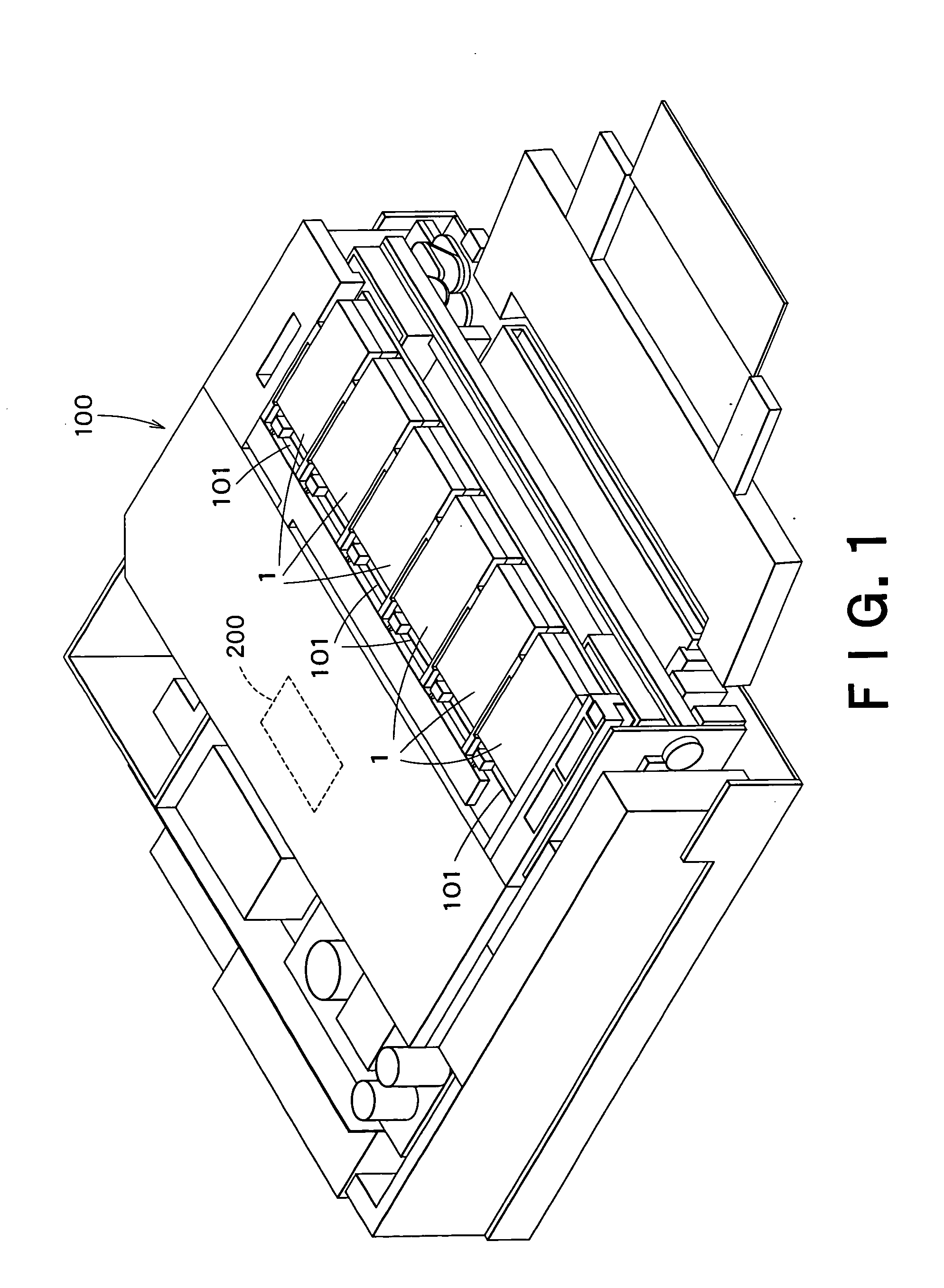
[0119]FIG. 1 is a perspective view showing the state that ink cartridges 1 are mounted in cartridge mounting units (liquid container holders) 101 of an ink jet recording apparatus 100 of this embodiment. In this example, six cartridge mounting units 101 are installed in the ink jet recording apparatus 100 and each cartridge mounting unit 101 is opened on the front of the ink jet recording apparatus 100. Further, the six cartridge mounting units 101 are arranged side by side on the same horizontal plane and the six ink cartridges 1 are flatwise arranged side by side. Ink fed from the ink cartridges 1 is ejected in drops toward a processed article such as a recording paper from an ink jet recording head (a liquid ejecting head) 200.

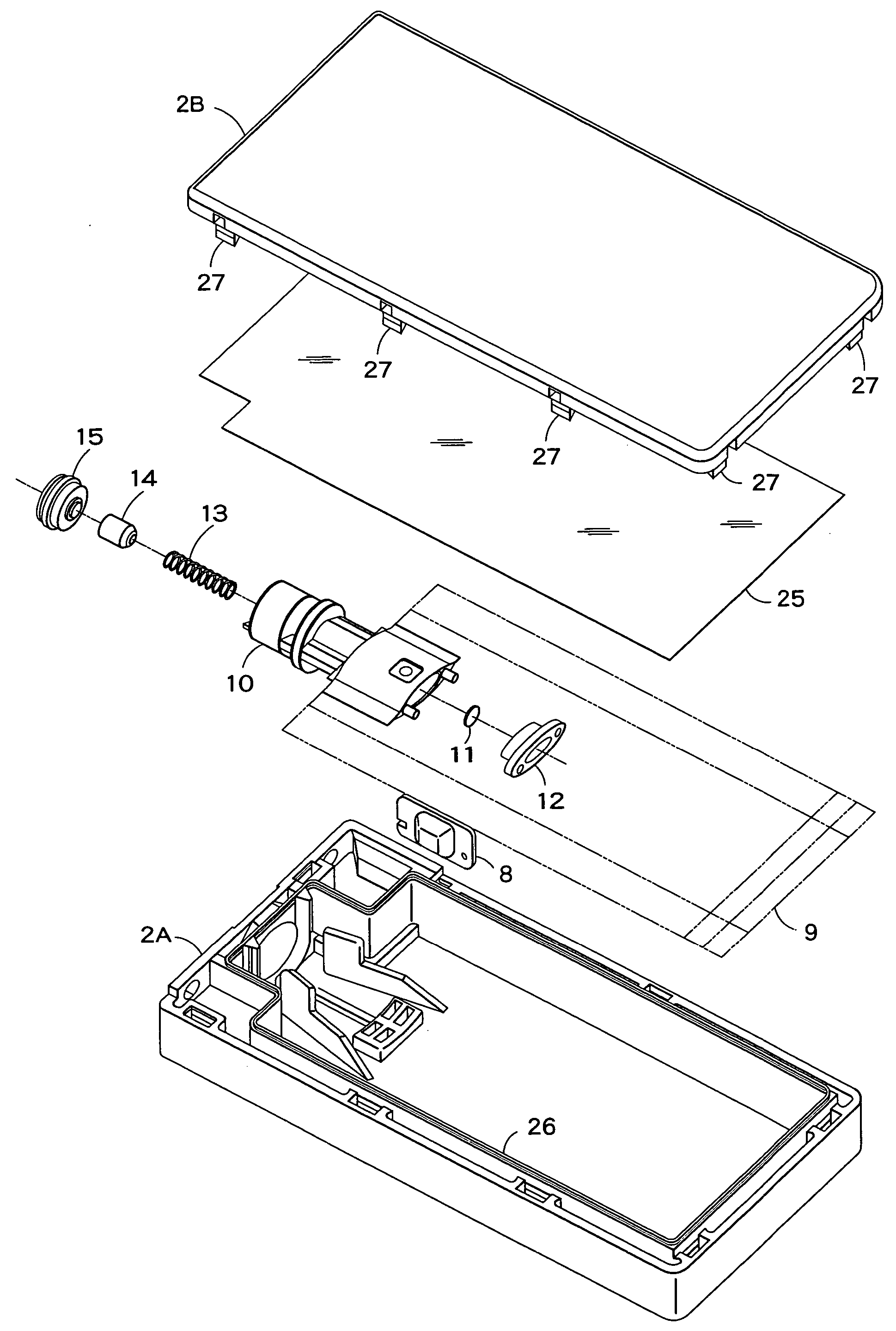
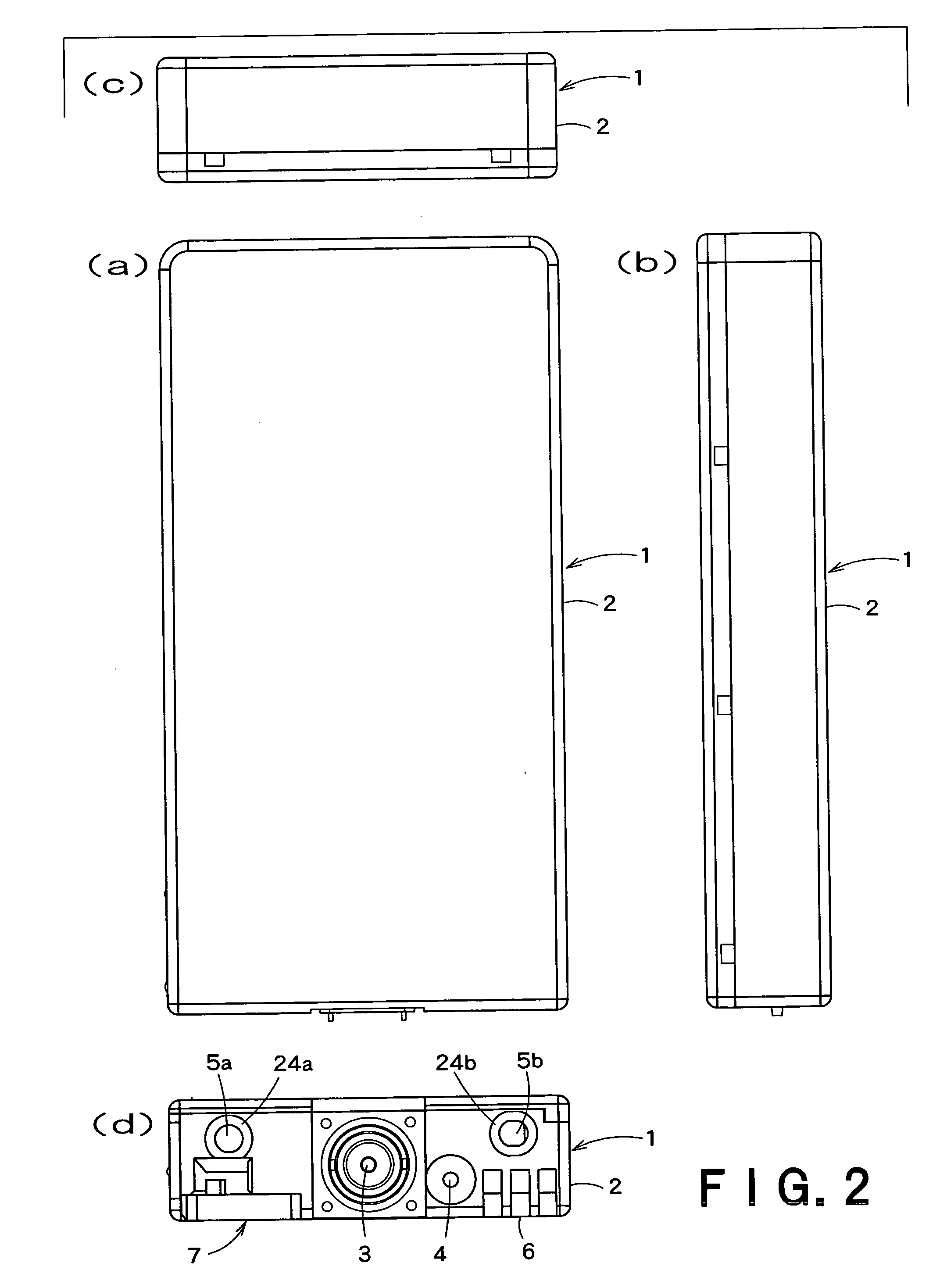
[0120] FIGS. 2 to 4 are drawings showing the appearance and shape of an i...


PUM


Abstract

A liquid ejecting apparatus of the present invention has a translationally movable member configured to be connected to a liquid container inserted in a container mounting unit, in link motion with a straight operation of the liquid container when inserting a liquid feed needle through a liquid feed port of the liquid container, translationally advance in the direction parallel with the straight operation, an apparatus side fixing structure for releasably restricting the movement of the liquid container in the mounting state in the pull-out direction, having a stopper pin to be stopped in a guide groove of a container side fixing structure formed in the liquid container, and apparatus side positioning structures installed in the translationally movable member, in cooperation with a container side positioning structure formed in the liquid container, for positioning the liquid container in a predetermined position to the translationally movable member. The liquid ejecting apparatus capable of connecting the liquid container to the translationally movable member arranged in the container mounting unit with high positioning precision is provided.

Description

BACKGROUND OF THE INVENTION [0001] 1. Field of the Invention [0002] The present invention relates to a liquid ejecting apparatus having a container mounting unit (a liquid container holder) in which a liquid container internally storing a liquid is removably mounted. [0003] 2. Description of the Related Art [0004] As a typical example of a conventional liquid ejecting apparatus, there is an ink jet recording apparatus having an ink jet recording head for image recording. As other liquid ejecting apparatuses, for example, an apparatus having a coloring material ejecting head used to manufacture color filters such as a liquid crystal display, an apparatus having an electrode material (conductive paste) ejecting head used to form electrodes such as an organic EL display and a face emission display (FED), an apparatus having a biological organic substance ejecting head used to manufacture biological chips, and an apparatus having a sample ejecting head as a precise pipette may be cited....

Claims


Application Information

Patent Timeline
Patent Type & Authority Applications(United States)
IPC IPC(8): B41J2/175
CPCB41J2/17553B41J2/1752B41J2/175
Inventor SEINO, TAKEOKUMAGAI, TOSHIOKIMURA, HITOTOSHIKOBAYASHI, ATSUSHIISHIZAWA, TAKU
Owner SEIKO EPSON CORP
Why Eureka
Try Eureka