Object tracking method and object tracking apparatus

a technology of object tracking and object tracking, which is applied in the direction of direction finders, instruments, television systems, etc., can solve the problems of delay time before the control operation is actually started, and achieve the effects of wide monitor range, low responsiveness, and high resolution

Inactive Publication Date: 2005-03-10
KOKUSA ELECTRIC CO LTD
View PDF10 Cites 40 Cited by
  • Summary
  • Abstract
  • Description
  • Claims
  • Application Information

AI Technical Summary

Benefits of technology

In order to overcome this problem, an object tracking method called the electronic tracking method has bee proposed in which a part of the input image is electronically enlarged and tracked without controlling the camera head or the image pickup lens. In this method, a part of the input image is cut out and enlarged, and therefore the pseudo control operation of the camera head is realized by adjusting the cut-out position. Further, the lack of the mechanical control operation makes it possible to solve the above-mentioned problem of low responsiveness of the devices for controlling the mechanical / optical tracking operation, and therefore stable tracking operation is assured. In this method, however, a part of the input image is cut out and enlarged, and therefore in the case where the resolution of the input image is low, the enlarged image undesirably appears in blocks (mosaic).
In the monitor system of automatic tracking type, it is important to monitor an object at a maximum zoom-up rate without adversely affecting the reliability of the object tracking function. The mechanical / optical tracking method has the advantage that the monitor range is wide and the image of the intruding object can be acquired with a high resolution. On the other hand, this monitor system is encountered with the problem of a considerable time length required before the intruding object is caught in an appropriate size at the center of the screen due to the low responsiveness of the camera head and the image pickup lens and the problem that the object cannot be tracked any longer once displaced out of the image.
The electronic tracking system has the advantage that an intruding object can be caught at high speed in an the appropriate size at the center of the screen. On the other hand, the problem is that an increased magnification of the input image at a low resolution leads to a blocked image, thereby making it impossible to acquire the detailed information on the intruding object and necessitating a wide-angle image pickup device.
The object of this invention, which has been developed in view of the aforementioned situation, is to provide an object tracking method and an object tracking apparatus wherein an object can be automatically tracked by an image pickup device at a sufficiently high speed to follow the motion of the object and the image of the object can be acquired with a sufficiently high resolution.

Problems solved by technology

In the case where the processing unit such as the microprocessing unit (MPU) of the monitor system judges that the camera head or the image pickup lens is required to be controlled, however, some delay time occurs before the control operation is actually started.

Method used


Image

  • Object tracking method and object tracking apparatus
  • Object tracking method and object tracking apparatus
  • Object tracking method and object tracking apparatus

Examples


Embodiment Construction

Embodiments of the invention are explained below with reference to the accompanying drawings. Identical or similar component parts are designated by the same reference numerals, respectively.

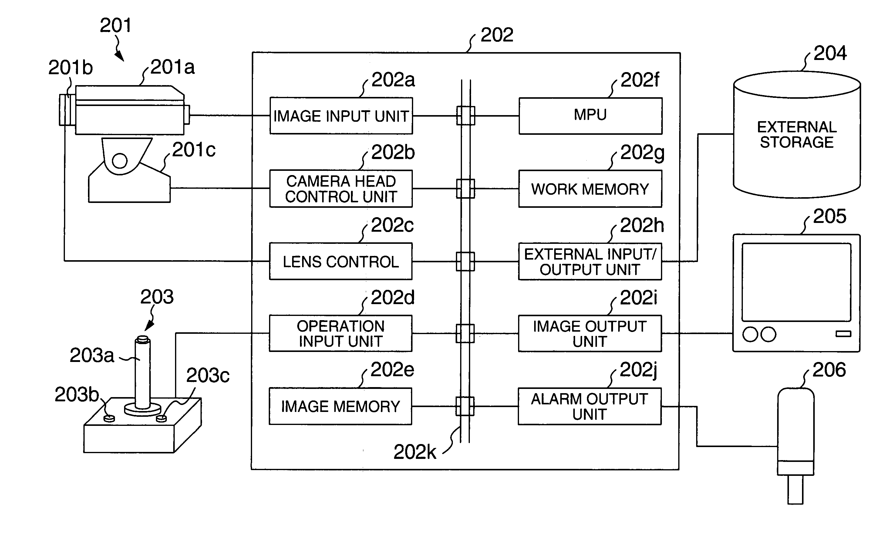
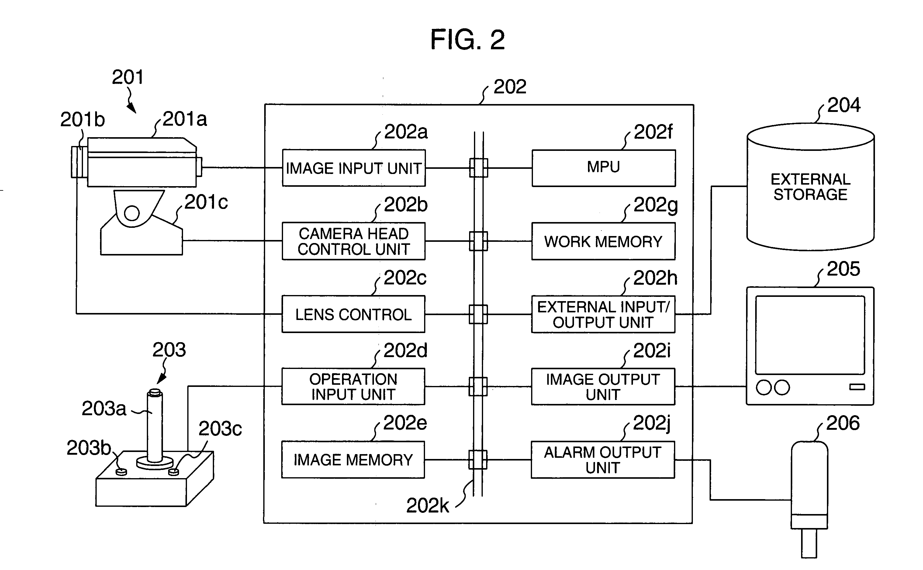
FIG. 2 shows an example of a hardware configuration of an image monitor device using an object tracking apparatus according to the invention. The image monitor according to this embodiment includes an image pickup device 201, a processing unit 202, an operating unit 203, an external storage unit 204, an image monitor 205 and an alarm lamp 206.

The image pickup device 201 includes a TV camera 201a, an image pickup lens 201b configured of a zoom lens, for example, and a camera head 201c configured of a swivel, for example.

The processing unit 202 includes an image input unit 202a, a camera head control unit 202b, a lens control unit 202c, an operating input unit 202d, an image memory 202e, a MPU 202f, a work memory 202g, an external input / output unit 202h, an image output unit 202i, an alarm o...


PUM


Abstract

An object tracking method and an object tracking apparatus for tracking an object in an image based on an image signal obtained from an image pickup device. At least one of the feature amounts including the position, size and the moving distance of the object in the image is detected, and based on the detection result, the image pickup lens of the image pickup device is controlled thereby to track the object. At the same time, the range of a partial area of the image is set based on the detection result, and the image of the partial area thus set is enlarged to a predetermined size and displayed on a monitor.

Description

BACKGROUND OF THE INVENTION The present invention relates to an object tracking method and an object tracking apparatus for tracking an object in an image picked up, or in particular to a technique for making it possible to track a moving object at a sufficiently high speed and acquire an image of the object with a sufficiently high resolution. A remote monitor system having an image pickup device such as a TV camera has been widely used. In many cases, the remote monitor system is what is called a manned monitor system in which an operator monitors an object while watching the image displayed on the monitor. In the manned monitor system, the operator is required to constantly watch the image displayed on the monitor and identify in real time an intruding object such as a person and an automobile entering the monitor range. This poses a considerable burden on the operator. In view of the fact that the concentration power of a person is limited, the manned monitor system may unavo...

Claims


Application Information

Patent Timeline
Patent Type & Authority Applications(United States)
IPC IPC(8): H04N7/18H04N5/232
CPCG08B13/19608G01S3/7865
Inventor ITO, WATARUUEDA, HIROTADA
Owner KOKUSA ELECTRIC CO LTD
Why Eureka
Try Eureka