An inverted microscope

a microscope and inverted technology, applied in the field of microscopes, can solve the problems of inability to precisely operate the cell, inability to measure current, and inability to physically interfere with the tv camera by micromanipulator,

Inactive Publication Date: 2005-03-10
OLYMPUS OPTICAL CO LTD
View PDF1 Cites 11 Cited by
  • Summary
  • Abstract
  • Description
  • Claims
  • Application Information

AI Technical Summary

Problems solved by technology

However, in case that the TV camera is attached to a side port of the microscope, the micromanipulator physically interferes with the TV camera as the micromanipulator is set at the lateral space of the microscope to precisely carry out the operation.
So, it becomes impossible to operate the micromanipulator if the TV camera is attached to the side port of the microscope.
As a result, it is not possible to precisely operate the cell, and measure the current when operating on the cell and measuring the current.
As a result, equipment for the microscope will be of large scale.
As a result, there is little choice but to locate the camera inside the microscope when trying to locate the camera at the position of the primary image.
That is, the design of the microscope is physically limited.
The secondary image is undesirable for observing low level lig

Method used


Image

  • An inverted microscope
  • An inverted microscope
  • An inverted microscope

Examples


first embodiment

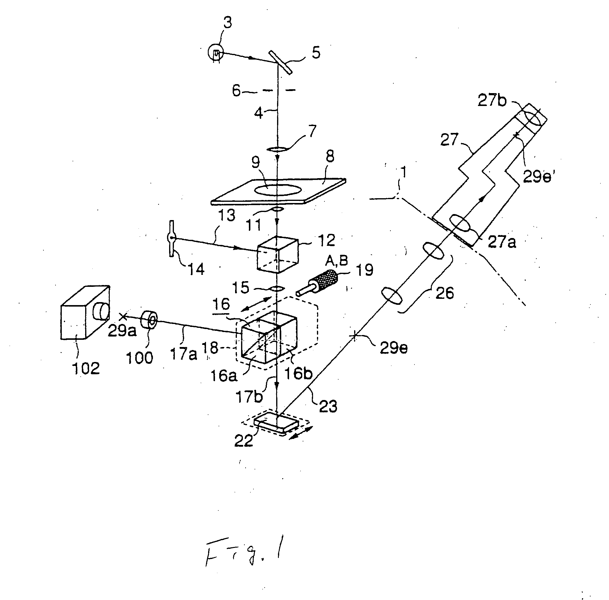
[0038] As explained above, this first embodiment includes the backside port 100 set in the backside of the frame 1, and the TV camera 102 attached to the backside port 100 by using the adapter 101. As a result, a micromanipulator of the type explained in connection with the prior art does not have physical interference with the TV camera 102, and may be operated precisely even if the micromanipulator is placed in the side space of the inverted microscope. In addition, by using the primary image as the image for the TV camera, a good quality image can be observed by the TV camera 102. That is, to take a weak observation image with high efficiency, an image based on the primary image is better than one based on the secondary image.

[0039] Furthermore, by using the backside port 100, it is not necessary to make a hole in a desk to locate the TV camera, and to provide a structure to insert between the desk and the bottom face of the microscope to raise the microscope. As a result, the eq...

second embodiment

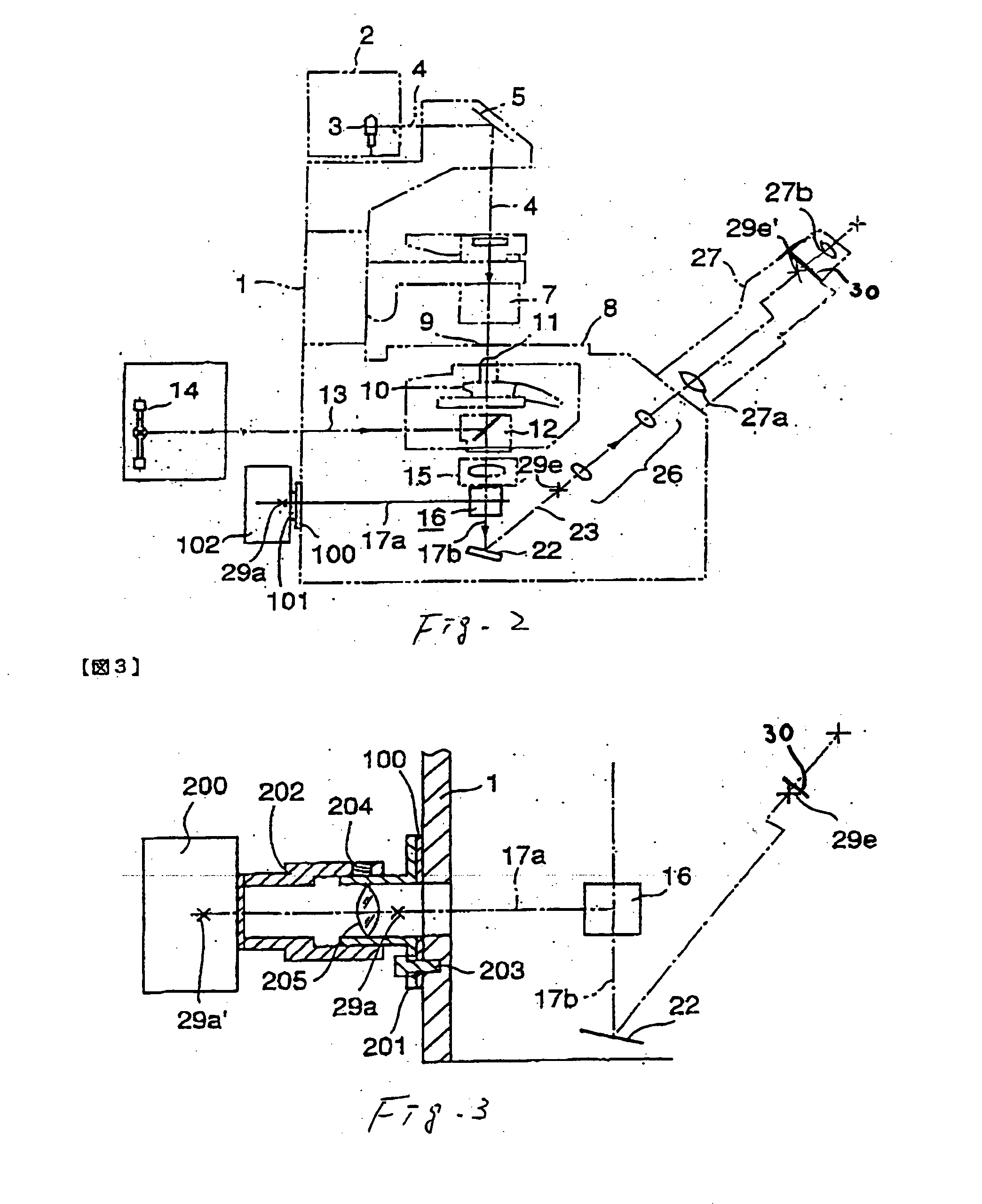
[0042] FIGS. 3 shows a schematic diagram of a substantial part of the inverted microscope of the invention. The components in FIG. 3 that are the same as those in FIGS. 1, and 2 are given the same reference numbers.

[0043] A typical inverted microscope includes a photo mask attached to the imaging port disposed in the observation optical path 17b, or a scale glass as explained in connection with the first embodiment. Either the photo mask or the scale glass can be inserted into the observation optical path 17b to be disposed in the focal plane which is one of the primary focal plane and the second focal plane. In this way, an image of the sample 9, which overlaps the photo mask or the scale glass, can be seen by the eye. In this case, checking of the image area of the camera is done indirectly by using the photo mask. Therefore, it is necessary that the center of the optical axis of the camera is aligned with the center of the photo mask. Also, the camera must be attached so that the...

third embodiment

[0056] In this third embodiment, it is easy to attach the TV camera 102 to the backside port 100.

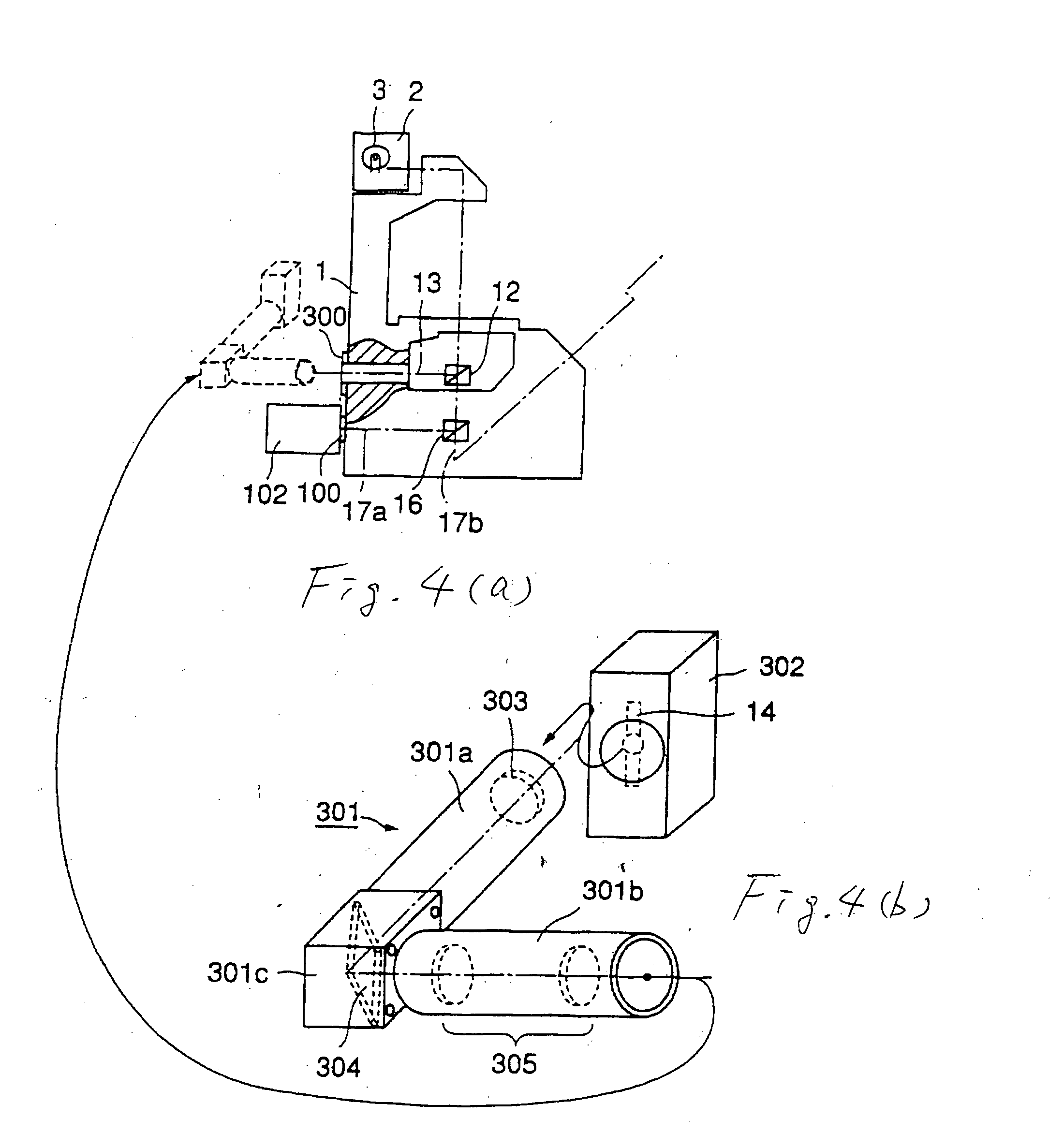
[0057] FIGS. 4(a), and 4(b) a schematic diagram of a substantial part of a third embodiment of the inverted microscope of the invention. The components in FIGS. 4(a), and 4(b) that are the same as those in FIGS. 1 and 2 are given the same reference numbers.

[0058] In FIGS. 4(a) and 4(b), the TV camera 102 is attached to the backside port 100, and an adapter 300 is placed in the position of the optical path of the reflected illumination light system 13. Also, the adapter 300 is placed at the backside of the frame 1. A reflected illuminator 301 is attached to the adapter 300. The reflected illuminator 301 is removable to the adapter 300. The reflected illuminator 301 includes a first reflected illuminator 301a, a second reflected illuminator 301b, and a relay tube 301c, which couples the first reflected illuminator 301a and the second reflected illuminator 301b. The first reflected illumin...


PUM


Abstract

A microscope includes an objective lens, an image-forming lens, a reflecting mirror for directing transmitted light passing through the image-forming lens to a front side of the microscope, and a first optical element for directing light from the image-forming lens to an imaging optical path running to a backside of the microscope. The first optical element is disposed between the image-forming lens and the reflecting mirror, with a port disposed in the imaging optical path, and an imaging device coupled to the port. The imaging device includes an image plane, the image plane substantially corresponding to the focal plane.

Description

CROSS REFERENCE TO RELATED APPLICATION [0001] This application is based on and claims priority of Japanese Patent Application No. Hei 12-78725 filed on Mar. 21, 2000, and Japanese Patent Application No. Hei 12-289466 filed on Sep. 22, 2000, the contents of which are incorporated herein by reference. BACKGROUND OF THE INVENTION [0002] 1. Field of the Invention [0003] The present invention relates to a microscope using an imaging device, such as a TV camera, or an optical camera. Also the present invention relates to a microscope for operating on a sample by using a laser beam, and for both observing the sample and carrying out the operation by using the laser beam at the same time. [0004] 2. Description of the Related Art [0005] An inverted microscope is disclosed in the U.S. Pat. No. 5,777,783. This inverted microscope can optically observe a sample via an eyepiece, and image a magnified image of the sample by means of a 35 mm camera, or a TV camera which is attached on a frame of t...

Claims


Application Information

Patent Timeline
IPC IPC(8): G02B21/00G02B21/36
CPCG02B21/36G02B21/0088
Inventor TAMURA, KEISUKEAONO, YASUSHI
Owner OLYMPUS OPTICAL CO LTD
Why Eureka
Try Eureka