Atomic force microscope measuring device

a microscope and microscope technology, applied in the direction of instruments, optical elements, fluorescence/phosphorescence, etc., can solve the problems of incompatibility of systems with modem optical techniques and compulsory use of second lasers, and achieve the effect of high efficiency and maximum excitation efficiency

Inactive Publication Date: 2017-01-26
ETH ZZURICH +1
View PDF5 Cites 9 Cited by
  • Summary
  • Abstract
  • Description
  • Claims
  • Application Information

AI Technical Summary

Benefits of technology

[0019]Preferably the wave length of the exciting light is in a range from 350 nm to 750 nm, it may be between 350 nm and 550 nm. Specifically a wave length of 405 nm may be used which has the additional advantage that it is far enough from many of the wave lengths used in fluorescence microscopy. However, depending on the cantilever material other wave lengths may be used as well. In particular, the wave length of the exciting light is chosen such that it is strongly absorbed by the cantilever.
[0020]Advantageously the posi

Problems solved by technology

Although there are Atomic Force Microscopes (AFM) that oscillate the cantilever by photothermal excitation, those systems are not compatible with modem optical techniques such as DIC, fluorescence microscopy, etc.
In addition, the device described herein does not use a laser to i

Method used


Image

  • Atomic force microscope measuring device
  • Atomic force microscope measuring device
  • Atomic force microscope measuring device

Examples


Embodiment Construction

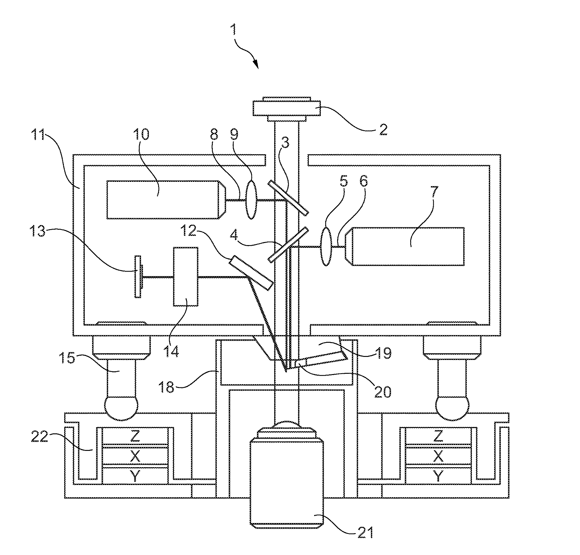
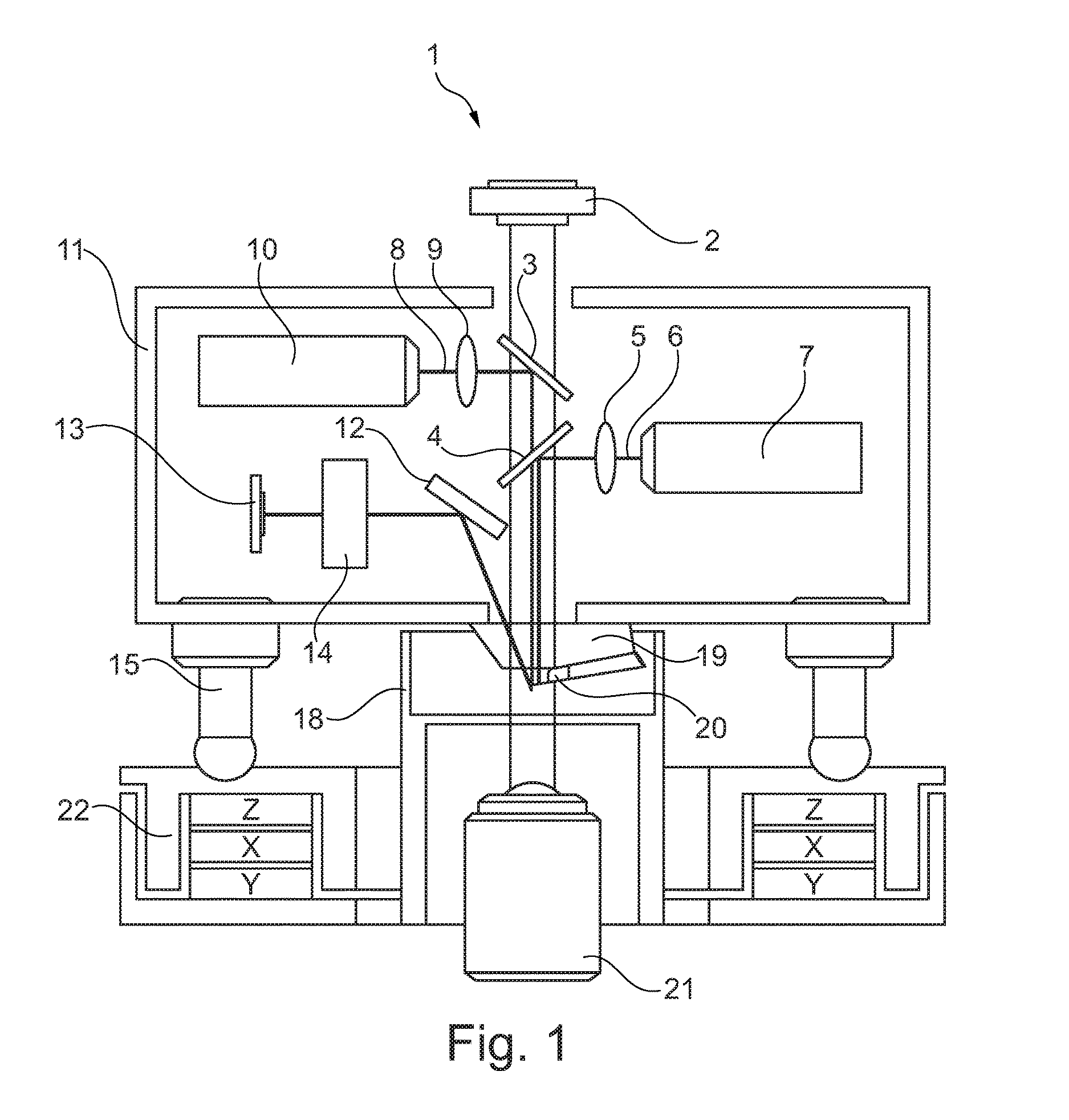
[0033]As can be seen the FIGS. 1 and 4, a 405 nm laser (7) is focused on the base of a microcantilever using a set of optical elements represented as (5) and the dichroic mirror (4) in order to photothermally excite the cantilever. The movement of the cantilever is detected using a beam deflection scheme but other methods can be also applied. The laser beam (8) is focused at the end of the cantilever using a set of optical elements represented as (9) and the dichroic mirror (3). The laser beam (8) reflects partially on the cantilever (20) and hits a gold mirror (12) that addresses the beam into a four quadrants photodetector (13) to be analyzed. Thanks to the optical properties of the dichroic mirrors (3) and (4) together with the cantilever holder (19), the cantilever itself which is totally or partially transparent and the sample holder (18), special light generated in (2) can go through the sample and be collected with an inverted microscope (21) for DIC imaging or similar techni...


PUM


Abstract

Atomic force microscope measuring device comprising a micro-cantilever and an intensity modulated laser exciting the cantilever, wherein the measuring device comprises an optical microscope, in particular a fluorescence microscope, a confocal microscope, a fluorescence energy transfer (FRET) microscope, a DIC and/or phase contrast microscope, all of those in particular construed as an inverted microscope.

Description

CROSS-REFERENCE TO RELATED APPLICATIONS[0001]This application is a 371 National Stage application of International Application No. PCT / EP2015 / 000349 tiled on Feb. 17, 2015, which claims priority of European Patent (EP) application Serial Number 14000560.4 filed on Feb. 17, 2014 and European Patent (EP) application Serial Number 14004244.1 filed on Dec. 16, 2014, all of which are incorporated herein by reference in their entireties.BACKGROUND OF THE INVENTION[0002]Field of the Invention[0003]The invention relates to an atomic force microscope measuring device comprising a micro-cantilever and an intensity modulated light source exciting the cantilever.[0004]Description of the Prior Art[0005]The invention proposed herein is based on Atomic Force Microscopy technology. It allows to determine topography, physical, chemical and biological properties of biological systems such as single cells, tissues, single molecules, protein crystal structures, over time and in physiological relevant e...

Claims


Application Information

Patent Timeline
IPC IPC(8): G01Q30/02G02B21/26G02B21/16G02B21/00G01N21/64G01N21/65
CPCG01Q30/025G01N21/6458G01N21/65G01N2201/06113G02B21/0088G02B21/26G02B21/16G01Q10/045G02B21/24G01N2021/6441B81B3/0029B81B2201/0214B81B2201/047B81B2203/0118G01G9/00G02B21/32
Inventor MARTINEZ-MARTIN, DAVIDMUELLER, DANIEL J.MARTIN, SASCHAGERBER, CHRISTOPH
Owner ETH ZZURICH
Why Eureka
Try Eureka