

Impeller and cutting elements for centrifugal chopper pumps
- Summary
- Abstract
- Description
- Claims
- Application Information
AI Technical Summary
Benefits of technology
Problems solved by technology
Method used
Image

Examples
Embodiment Construction
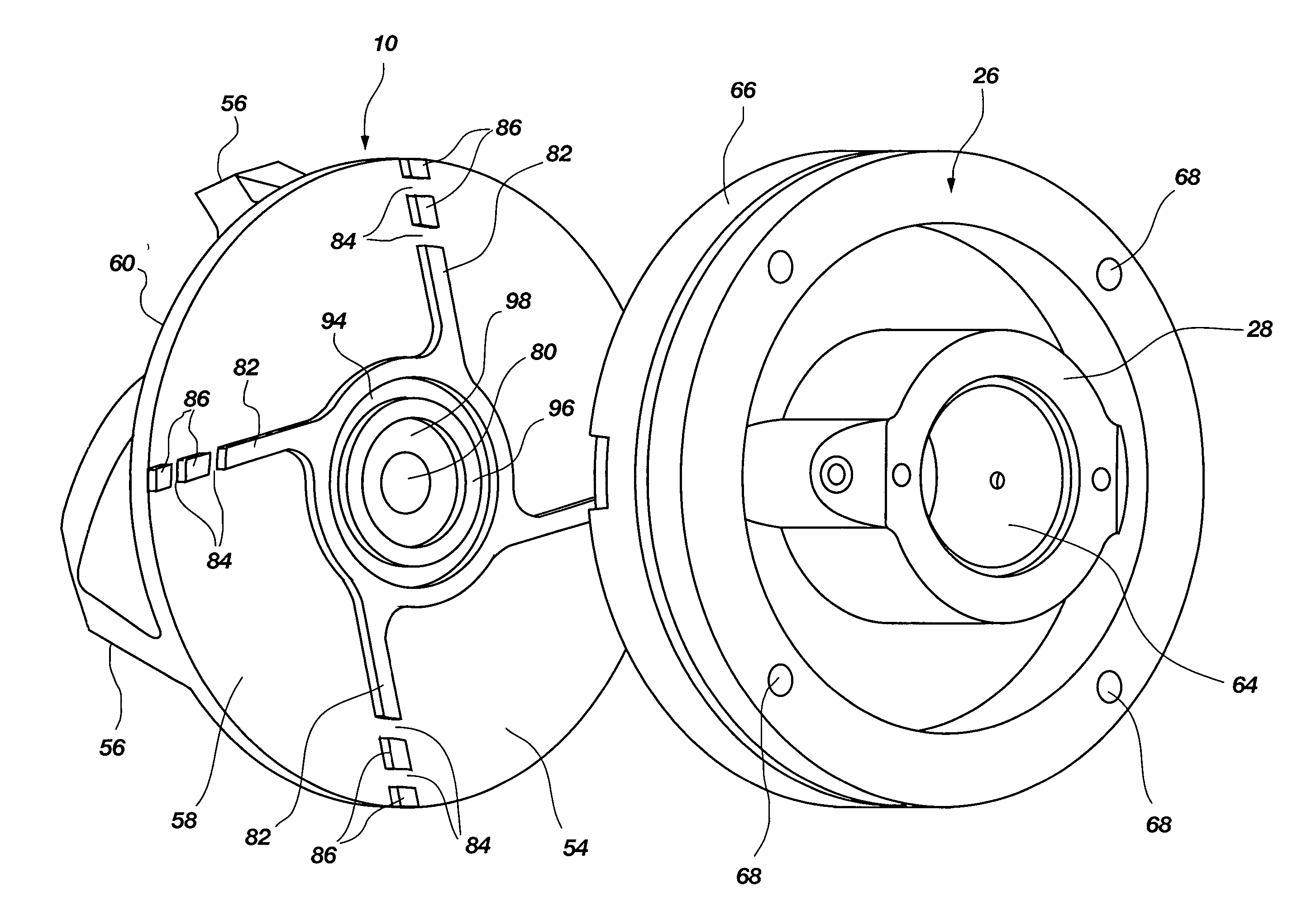
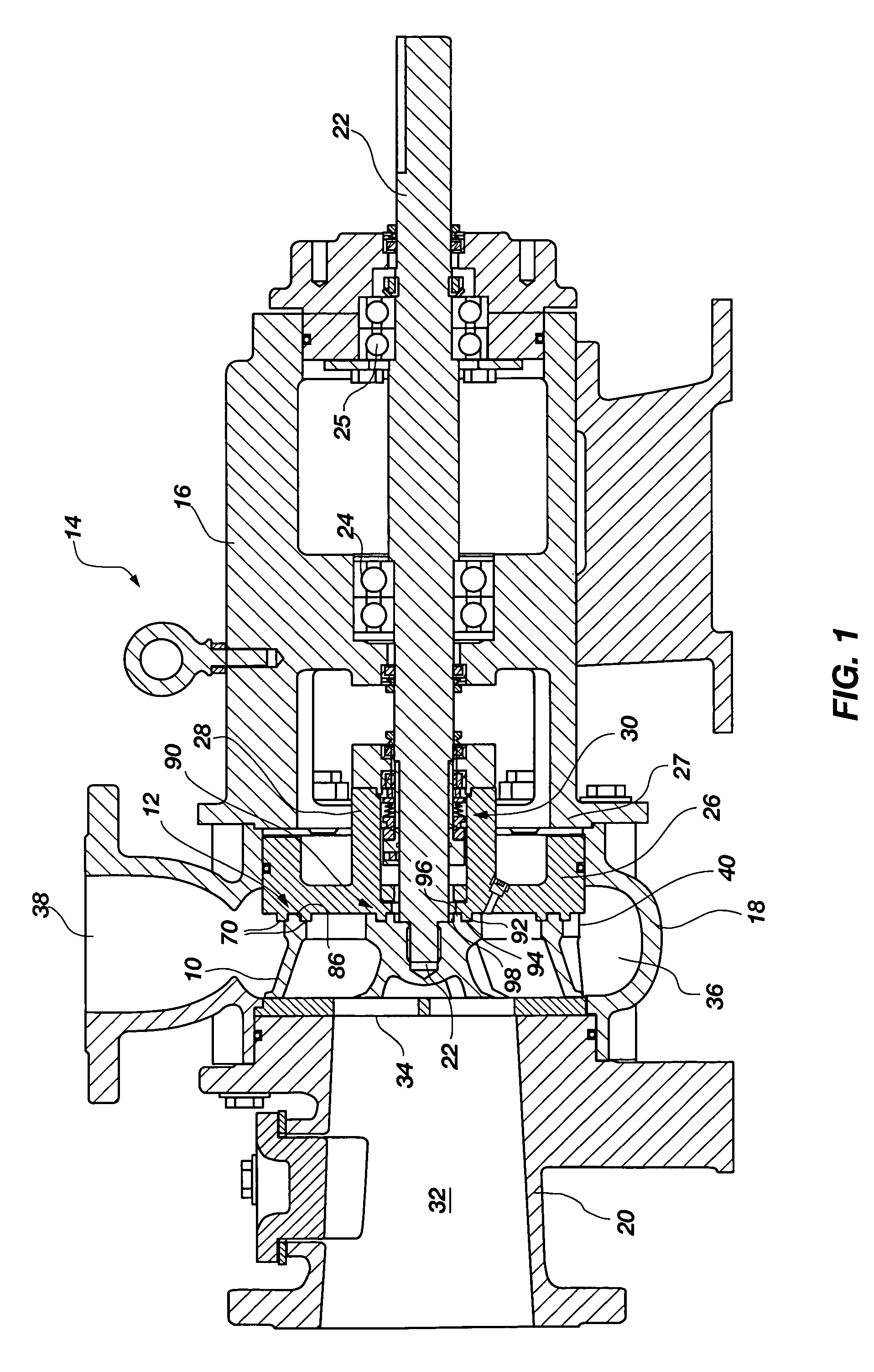
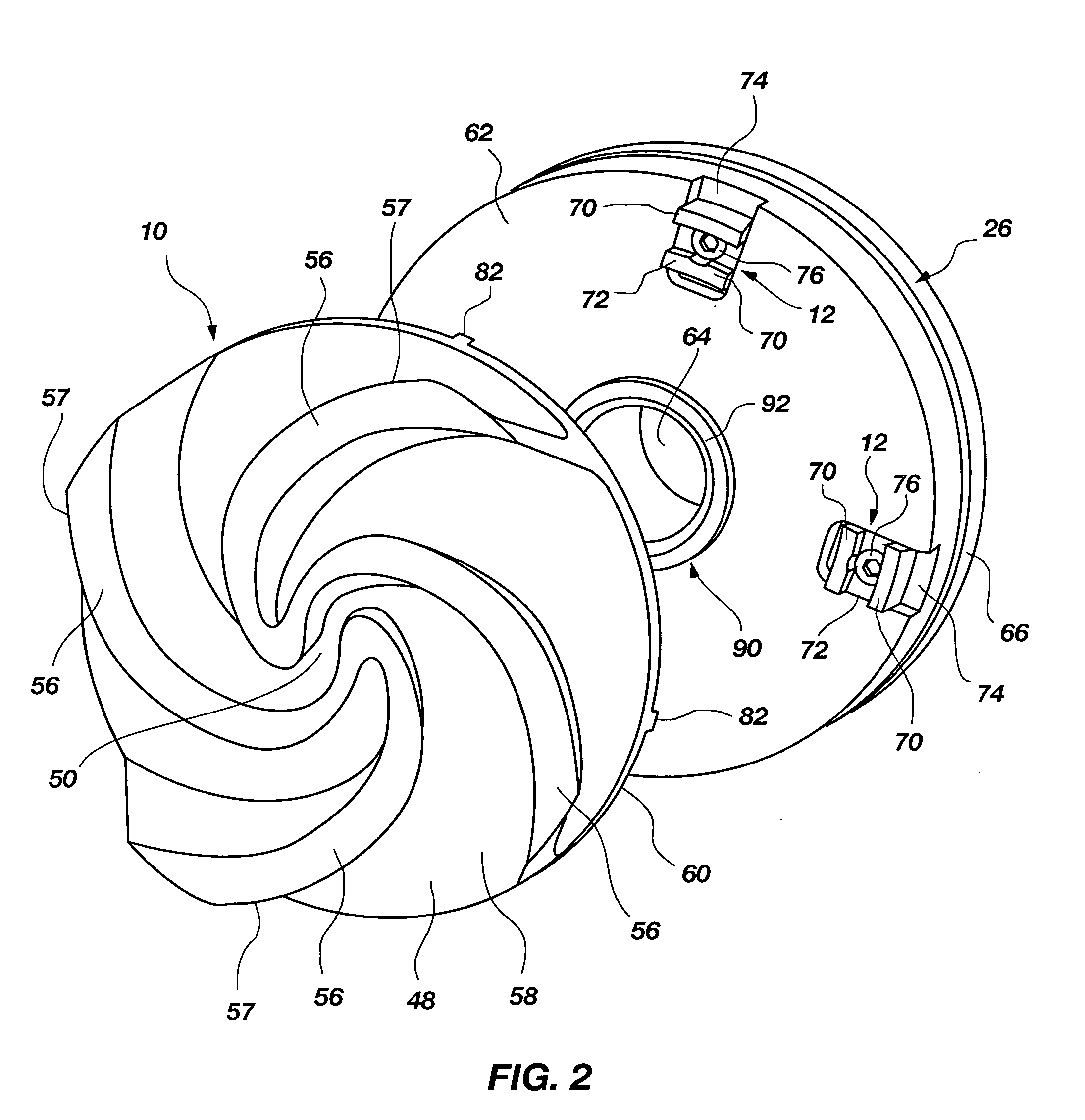
[0024]FIG. 1 illustrates in longitudinal cross section one exemplar configuration of a centrifugal chopper pump constructed with the impeller 10 and cutting elements 12 of the present invention. The centrifugal chopper pump 14 generally comprises a pump casing that is shown in FIG. 1 as comprising a drive casing 16, a volute casing 18 that is secured to the drive casing 16, and a suction casing 20 that is secured to the volute casing 18.
[0025] The drive casing 16 is generally structured to receive a drive shaft 22 which extends through the drive casing 16 and into the volute casing 18. Bearing assemblies 24 and 25 are generally positioned within the drive casing 16 to support the drive shaft 22. The drive shaft 22 extends through the drive casing 16 and is attached to the impeller 10, which is positioned within the volute casing 18.
[0026] The drive shaft 22 may also extend through a back plate 26 that is positioned between the drive casing 16 and impeller 10. The back plate 26 is ...
PUM
 Abstract
Description
Claims
Application Information