Balanced transmission cable connector

a transmission cable and connector technology, applied in the direction of coupling device connection, connection contact member material, coupling protective earth/shielding arrangement, etc., can solve the problems of accelerating transmission speed of signals being handled by computers and servers, affecting transmission characteristics, and shielding adjacent transmission paths. , to achieve the effect of improving transmission characteristics and high-speed signal transmission

Inactive Publication Date: 2005-03-10
FUJITSU COMPONENENT LTD
View PDF3 Cites 23 Cited by
  • Summary
  • Abstract
  • Description
  • Claims
  • Application Information

AI Technical Summary

Benefits of technology

[0011] The present invention has been conceived in response to one or more problems of the related art, and its object is to provide a balanced transmission cable connector with improved transmission characteristics for high speed signal transmission.
[0017] In an aspect of the present invention, first and second signal wires and a drain wire of a balanced transmission cable are connected to first and second signal contacts and a ground contact of a plug structure, and the ground contact is arranged to be longer than the first and second signal contacts. Accordingly, a shielding effect may be improved between a transmission path for transmitting a balanced signal and an adjacent transmission path for transmitting another balanced signal, and transmission characteristics may be improved so that high speed signal transmission may be realized.

Problems solved by technology

However, in the balanced transmission cable connector 10, problems exist with regard to shielding adjacent transmission paths from one another at the relay substrate 12.
In recent years and continuing, the transmission speed of signals being handled by computers and servers is accelerating, and in turn, influences on the transmission characteristics due to poor shielding at the relay substrate 12 are becoming a problem.

Method used


Image

  • Balanced transmission cable connector
  • Balanced transmission cable connector
  • Balanced transmission cable connector

Examples


Embodiment Construction

[0032] In the following, preferred embodiments of the present invention are described with reference to the accompanying drawings.

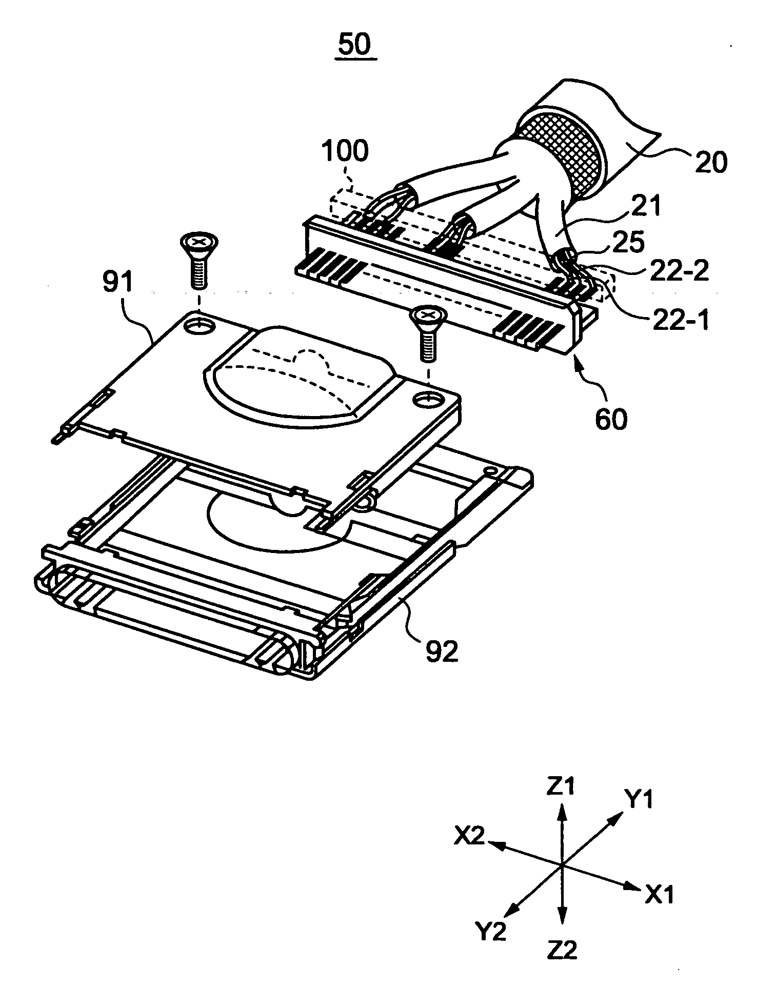
[0033]FIGS. 4 and 5 illustrate a balanced transmission cable connector 50 according to a first embodiment of the present invention. It is noted that directions X1-X2, Y1-Y2, and Z1-Z2 respectively correspond to width directions, length directions, and height directions of the balanced transmission cable connector 50. Also, the direction Y1 corresponds to a front side and the direction Y2 corresponds to a back side.

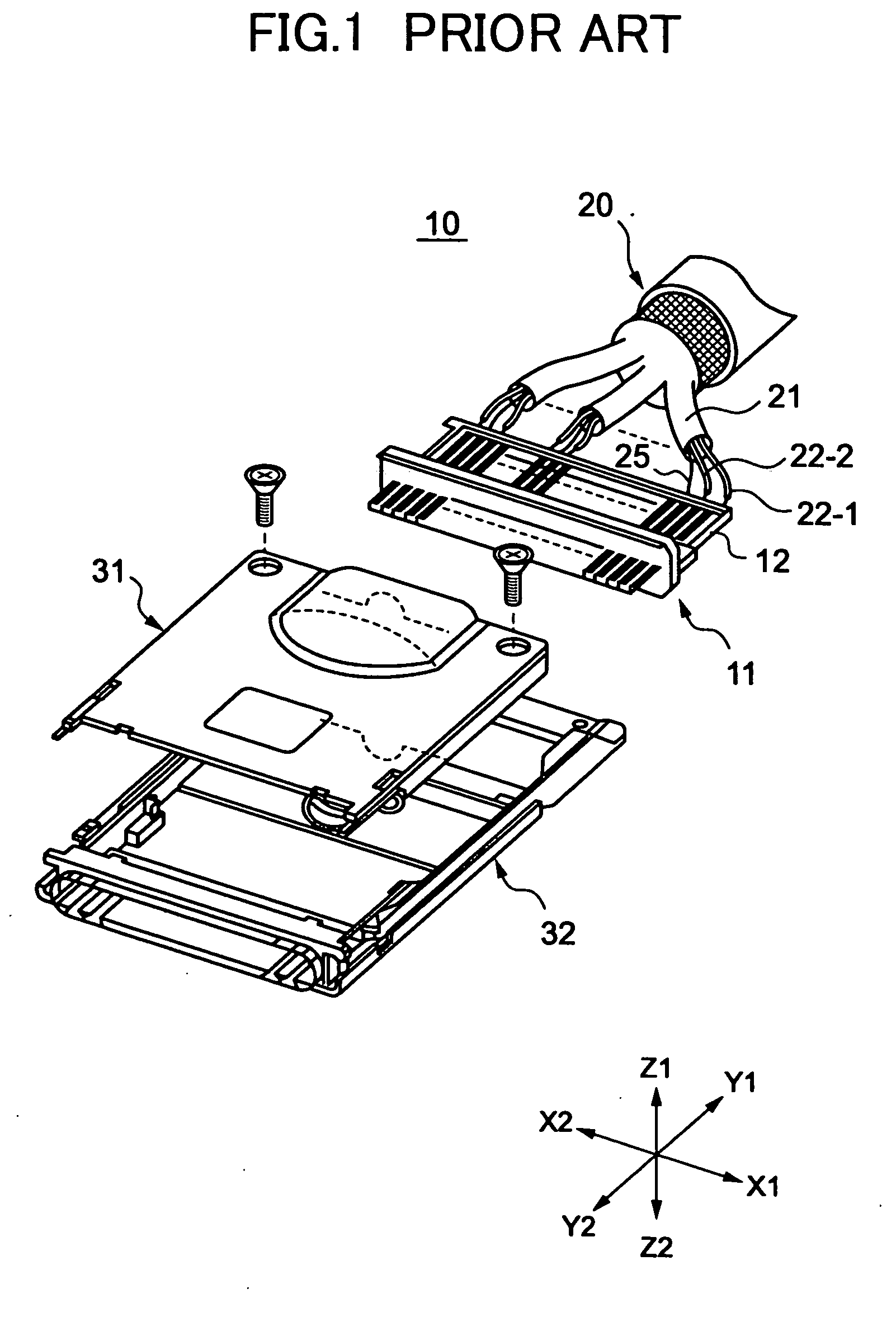
[0034] The balanced transmission cable connector 50 differs from the balanced transmission cable connector 10 shown in FIGS. 1 and 2 in that it does not include the relay substrate 12. The extended ends of the balanced transmission cable 20 are directly connected to a plug structure 60 through soldering, and shield covers 91 and 92 cover the plug structure 60, a wire arranging member 100, and the end portion of the balanced transmission cable ...


PUM


Abstract

A balanced transmission cable connector with improved high speed signal transmission characteristics is realized by directly connecting a balanced transmission cable to a plug structure. The plug structure includes a block unit, a ground contact, and adjacent pairs of a first signal contact and a second signal contact. The ground contact and the adjacent pairs of the first signal contact and the second signal contact are aligned in an alignment direction with respect to one another and are held by the block unit. The ground contact is disposed in between the adjacent pairs of the first signal contact and the second signal contact. The first signal contact includes a first signal wire connecting portion to which a first signal wire of the balanced transmission cable is connected, and the second signal contact includes a second signal wire connecting portion to which a second signal wire of the balanced transmission cable is connected. The ground contact includes a drain wire connecting portion to which a ground wire of the balanced transmission cable is connected.

Description

BACKGROUND OF THE INVENTION [0001] 1. Field of the Invention [0002] The present invention relates generally to a balanced transmission cable connector, and particularly to a balanced transmission cable connector that is used for high speed signal transmission. [0003] 2. Description of the Related Art [0004] As data transmission schemes for transmitting data, a normal transmission scheme using one wire for each set of data may be used, or a balanced transmission scheme using a pair of wires for each set of data may be used to simultaneously transmit a (+) signal that is to be transmitted and a (−) signal in an opposite direction of the (+) signal but of the same size. In the balanced transmission scheme, influence from noise may be reduced compared to the normal transmission scheme. Thus, the balanced transmission scheme is becoming increasingly popular. A balanced transmission cable connector used in the balanced transmission scheme includes a balanced transmission cable, a plug tha...

Claims


Application Information

Patent Timeline
Patent Type & Authority Applications(United States)
IPC IPC(8): H01R13/6471H01R13/658H01R13/6585H01R13/6593H01R24/56
CPCH01R9/032H01R13/65807H01R24/562H01R13/6471H01R13/6585H01R13/6593H01R2107/00H01R13/65912
Inventor AKAMA, JUNICHIMORIYAMA, SATOSHIKOBAYASHI, MITSURUSATA, YOSHINORI
Owner FUJITSU COMPONENENT LTD
Why Eureka
Try Eureka