Microbial concentration system

a concentration system and concentration chamber technology, applied in the field of liquid centrifuge separation chambers, can solve the problems of insufficient sampling capability of present centrifuge systems and centrifuge separation chambers, speed or reliability not necessary for many applications, and requires rapid collection and analysis, so as to achieve the effect of efficient sample collection

Inactive Publication Date: 2005-03-10
BRADLEY BRUCE J
View PDF55 Cites 43 Cited by
  • Summary
  • Abstract
  • Description
  • Claims
  • Application Information

AI Technical Summary

Benefits of technology

[0019] In either the radial or non-radial configured chamber described above, the coll...

Problems solved by technology

Present centrifuge systems and centrifuge separation chambers do not provide sufficient sampling capabilities, detection sensitivity, speed or reliability necessary for many applications.
Add...

Method used


Image

  • Microbial concentration system
  • Microbial concentration system
  • Microbial concentration system

Examples


Embodiment Construction

[0040] While the invention is susceptible to various modifications and alternative constructions, certain illustrated embodiments thereof have been shown in the drawings and will be described below in detail. It should be understood, however, that there is no intention to limit the invention to the specific form disclosed, but, on the contrary, the invention is to cover all modifications, alternative constructions, and equivalents falling within the spirit and scope of the invention as defined in the claims.

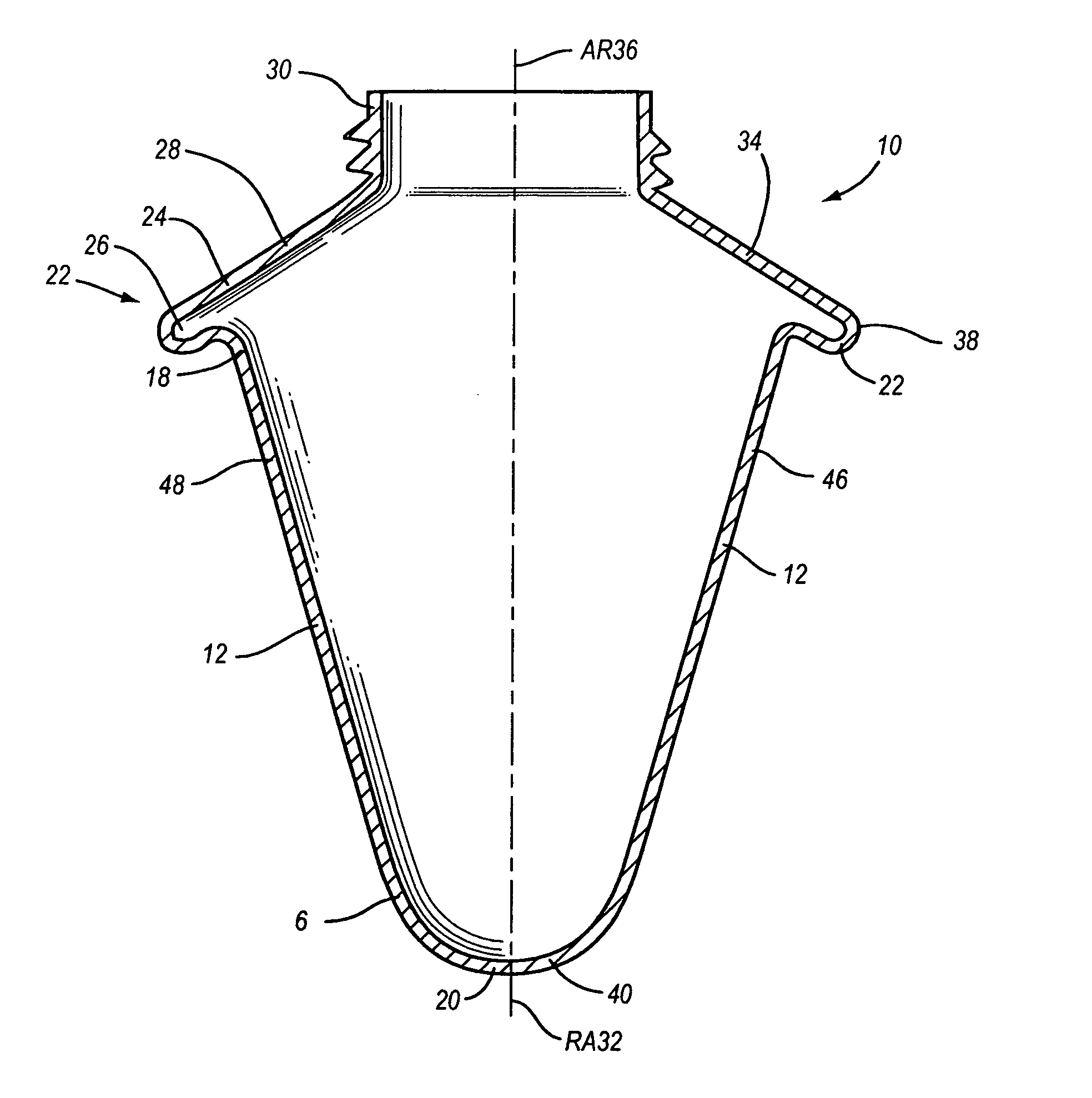
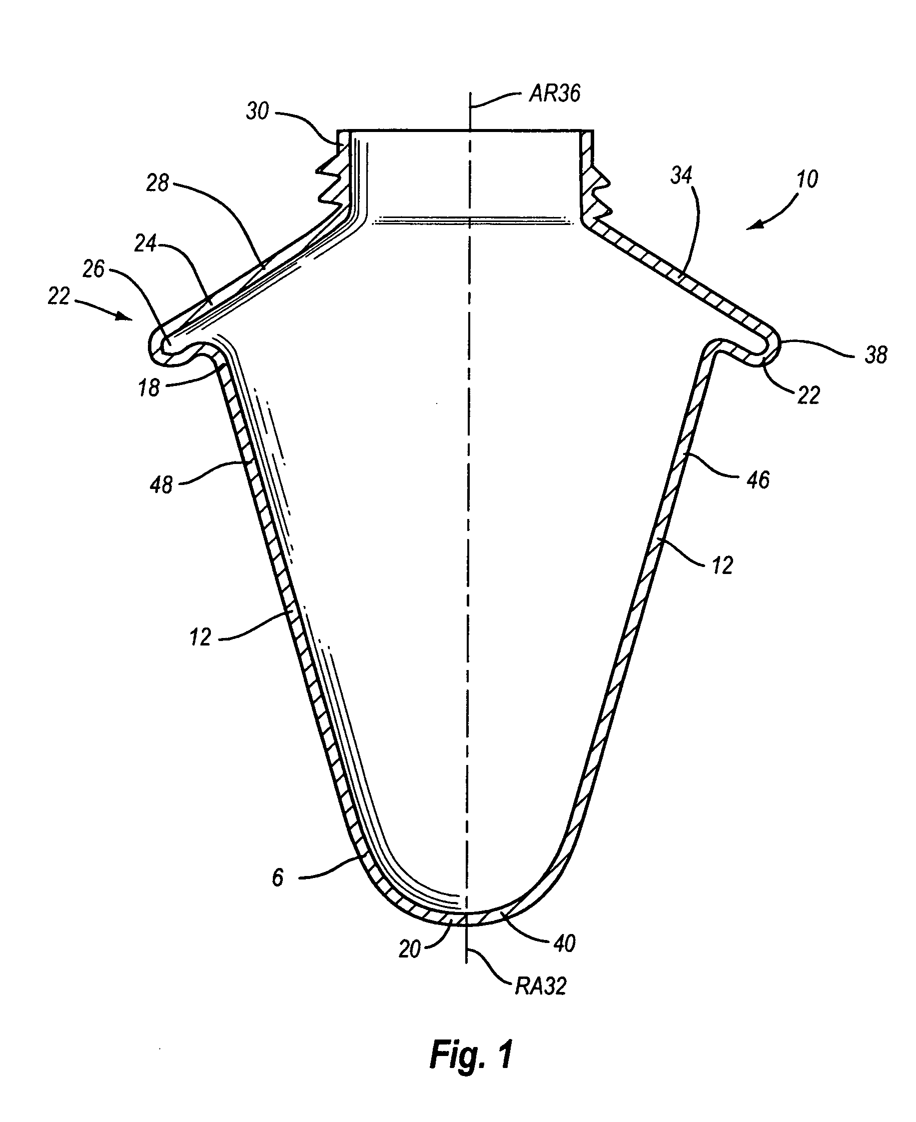
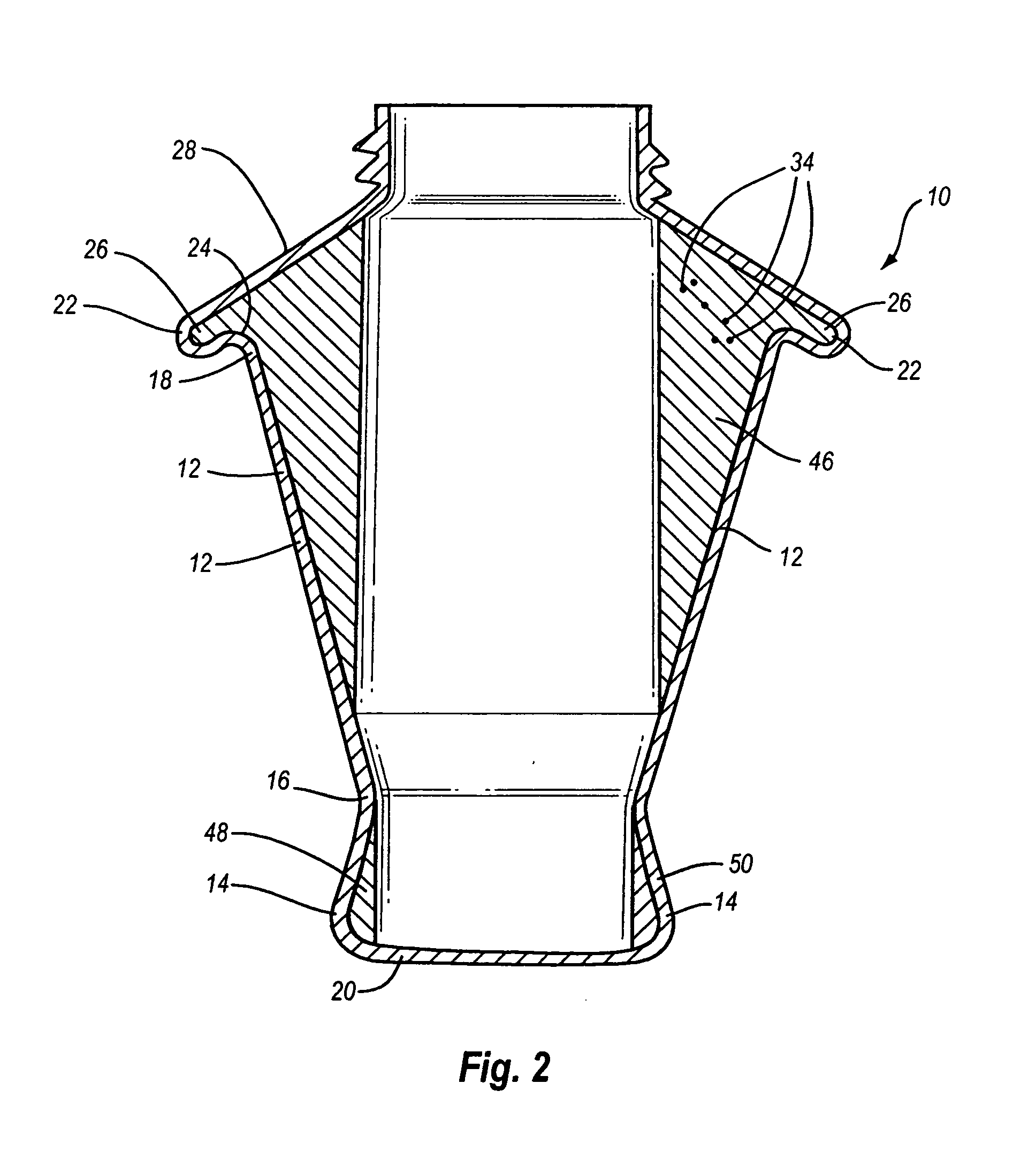
[0041]FIGS. 1-11B show several different preferred embodiments of the invention. FIG. 1 shows one preferred version of the collection vessel of the invention. FIG. 1 shows a centrifuge separation chamber 10 of the invention. It includes a first frustoconical chamber sidewall 12 attached to a chamber base 20. In this case, the chamber base 20 forms a convex base 40. Other versions of the device include a generally flat chamber base 20. The first frustoconical chamber sidewall 12 ...


PUM


Abstract

A centrifuge separation chamber of particular use for separating microbes. The chamber has an upwardly flared conical shape, and a sample collecting groove at its widest point. Sample is collected in the sample groove as the chamber spins. When slowed to a stop, the supernatant sinks to the bottom of the chamber, leaving the sample in the sample groove where it can be easily accessed.

Description

PRIORITY [0001] This application claims the priority date of the provisional application entitled HIGH EFFICIENCY LIQUID MICROBIAL CONCENTRATION SYSTEM filed by Bruce J. Bradley on Jul. 30, 2003 with application Ser. No. 60 / 491,578.BACKGROUND OF THE INVENTION [0002] 1. Field of the Invention [0003] The present invention relates generally to the field of liquid centrifuge separation chambers. More particularly, the present invention provides a high efficiency liquid microbial concentration system using a collection groove positioned at the point of peak relative centrifugal force. [0004] 2. Background Information [0005] Centrifuge separation chambers are used to sample microbes for various applications. In many cases, the effectiveness of the microbial recovery depends on the sampling procedures and the concentrations available. For example, rotary bucket centrifuges are commonly used in laboratories for routine separation of small particles, such as bacteria, from the suspension liq...

Claims


Application Information

Patent Timeline
IPC IPC(8): B01L3/14B04B5/04B04B5/10B04B7/08B04B11/04C12M1/26G01N1/02
CPCB01L3/5021B01L2300/0858B04B5/04C12M33/10B04B7/08B04B11/04G01N2001/022B04B5/10
Inventor BRADLEY, BRUCE J.
Owner BRADLEY BRUCE J
Why Eureka
Try Eureka