Intraoperative imaging system

a technology of imaging system and intraoperative, applied in the direction of radiation beam directing means, instruments, applications, etc., can solve the problems of reducing the effectiveness of surgery, affecting the operation, and affecting the operation efficiency, so as to reduce the size of the operation, facilitate the operation, and facilitate the movement.

Active Publication Date: 2005-03-10
XORAN TECH
View PDF20 Cites 69 Cited by
  • Summary
  • Abstract
  • Description
  • Claims
  • Application Information

AI Technical Summary

Benefits of technology

[0004] The present invention provides an imaging system that is particularly advantageous for intraoperative use, although it may be used anywhere that space and easy setup is important. Generally, the imaging system includes a source and a detector that can be quickly and easily moved out of the way after scanning. Since much of the bulk of the known CT scanners comes from the structure that moves the source and detector along precisely controlled, predetermined paths, one way that the imaging

Problems solved by technology

The problem with using the pre-operative image is that the object selected may have shifted between the time the pre-operative image was taken and the time of surgery.
In matters like intercranial surgery the tolerance for variations is low, thus even small changes between the image and actual subject may cause problems and make the surgery less effective.
However, selecting the area to be scanned, setting up the

Method used


Image

  • Intraoperative imaging system
  • Intraoperative imaging system
  • Intraoperative imaging system

Examples


first embodiment

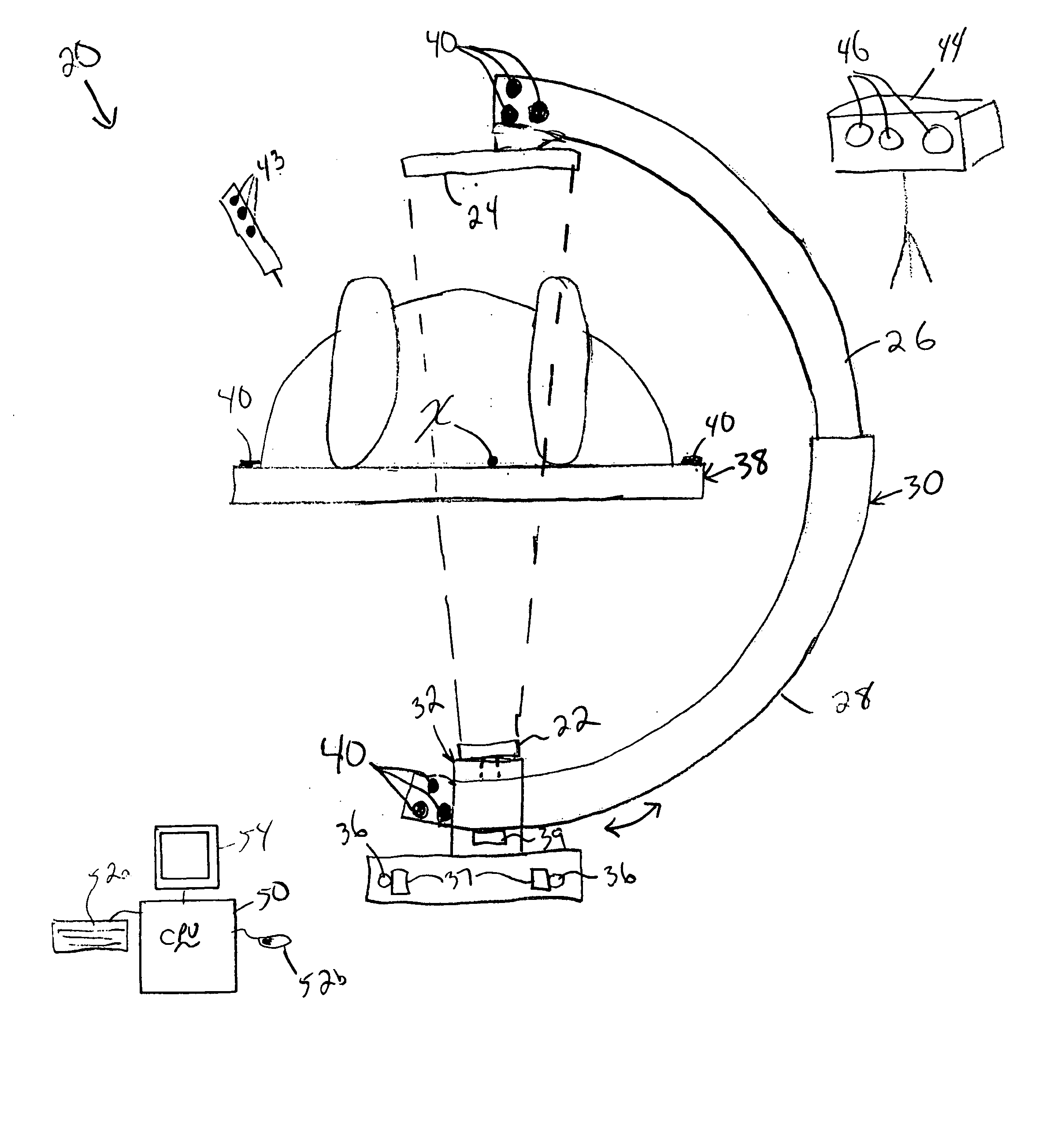
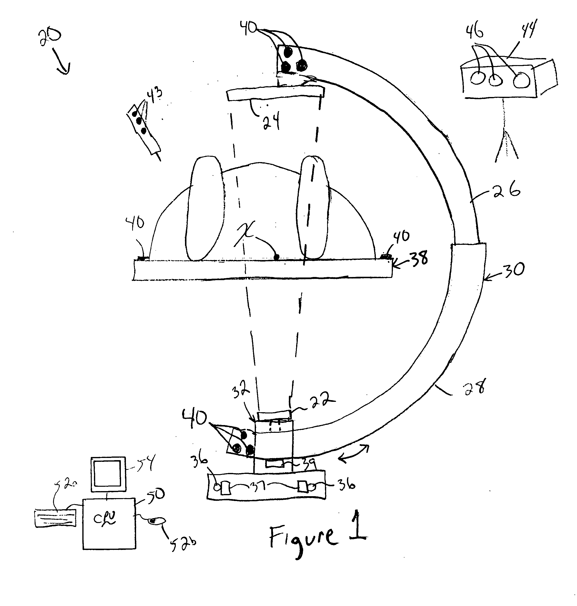
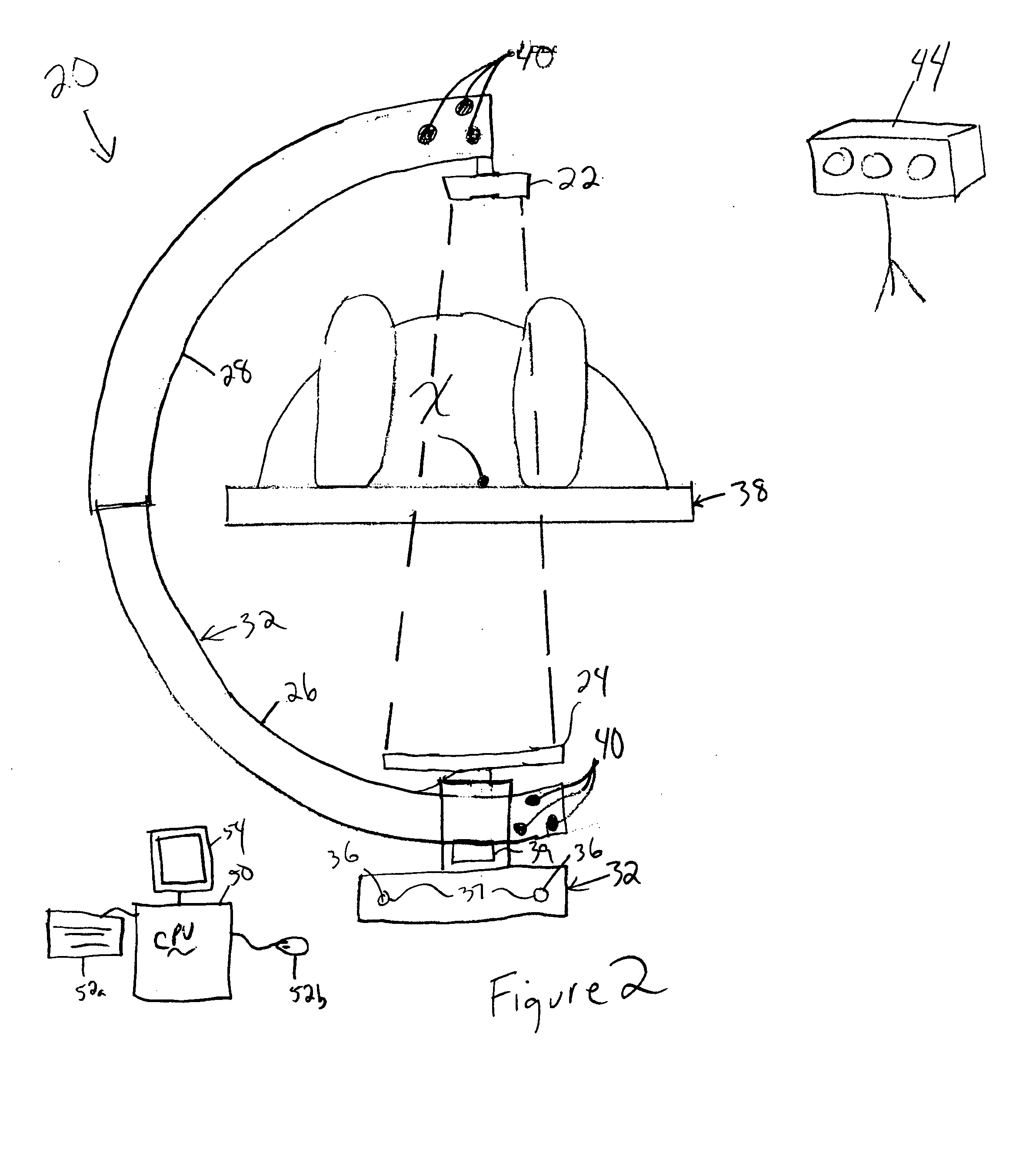
[0014] an intraoperative imaging system 20 according to the present invention is shown in FIGS. 1-4. The imaging system 20 is particularly useful for image-guided surgery or other applications where intra-operative imaging would be desired. Although applicable for other types of imaging systems, the present invention will be described with respect to an intra-operative CT scanning system 20 for illustrative purposes. Referring to FIG. 1, the CT scanning system 20 includes a source 22 and detector 24 mounted at outer ends of a first c-arm section 26 and a second c-arm section 28, respectively. The source 22 may be a cone-beam x-ray source 22. The detector 24 may be a flat panel detector 24 having a converter for converting x-rays into light which is detected by an array of photodetectors.

[0015] The first and second c-arm sections 26, 28 are slidably connected to one another, such that first c-arm section 26 slides telescopes within the second c-arm section 28. The first and second c-...

second embodiment

[0024] the system 20a is shown in FIG. 5. In FIG. 5, the c-arm section 28a is slidably mounted along the inner arc surface of the c-arm section 26a. The c-arm sections 26a, 28a are shown in the collapsed position in FIG. 5. Otherwise, the operation is as described above.

third embodiment

[0025] A third embodiment is shown in FIG. 6, which is a section view through the carriage 32b. In this embodiment, the c-arm sections 26b, 28b are separately supported in the carriage 32b, with separate motors 39b driving each about the axis during scanning. Although the source 22 and detector 24 are offset slightly along the x-axis, they can be tilted slightly to accommodate this offset.


PUM


Abstract

An imaging system includes a source and a detector that can be quickly and easily moved out of the way after scanning. During scanning, the actual paths that the source and detector travel are tracked, such as by an associated surgical navigation system tracking system. The actual locations of the source and detector during each x-ray image are used in the image reconstruction algorithm. Since the actual locations are used in the algorithm, the locations do not have to be as precisely controlled. In one embodiment, the source and detector are mounted proximate outer ends of first and second c-arm sections. The first and second c-arm sections are extendable to form a complete c-arm and retractable to a collapsed position when not in use. In the disclosed embodiment, the c-arm sections are mounted to a base or carriage under the patient support surface (such as the surgical table).

Description

[0001] This application claims priority to U.S. Provisional Application Ser. No. 60 / 493,195, filed Aug. 7, 2003.BACKGROUND OF THE INVENTION [0002] Image guided surgery is becoming more common, especially in the areas of inter-cranial surgery. Systems are utilized to take data gathered from pre-operative scans by MRI, CT scanners, ultrasounds, or the like. The data is used to generate a three-dimensional image to guide a surgeon during an operation. Often this includes some method for tracking an instrument location with respect to the image displayed by the system. Generally, the image is registered relative to locators attached to the patient. Then, the position and orientation of the surgical instruments is registered and tracked relative to the image and the patient so that the location and orientation of the instruments relative to the image is continuously displayed while the surgeon performs the surgery. [0003] The problem with using the pre-operative image is that the object ...

Claims


Application Information

Patent Timeline
IPC IPC(8): A61B6/00A61B6/03
CPCA61B6/032A61B6/4405A61B6/4411A61B19/5244A61B6/466A61B6/547A61B6/589A61B6/4441A61B34/20
Inventor SUKOVIC, PREDRAGCLINTHORNE, NEALBAIR, NATHANIEL
Owner XORAN TECH
Why Eureka
Try Eureka