Covered stent and method of covering a stent

a stent and stent technology, applied in the field of stent and stent covering, can solve the problems of increasing the incidence and achieve the effect of minimizing the risk of stent covering tearing during expansion

Inactive Publication Date: 2005-03-10
ATRIUM MEDICAL
View PDF18 Cites 19 Cited by
  • Summary
  • Abstract
  • Description
  • Claims
  • Application Information

AI Technical Summary

Benefits of technology

[0004] The present invention provides a covered stent that predictably and dependably expands to an increased diameter state at relatively low deployment pressures while concomitantly minimizing the risk of tearing of the stent covering during expansion. The stent covering is comprised of an inner cover and an outer cover that are po

Problems solved by technology

However, they also increase the incid

Method used


Image

  • Covered stent and method of covering a stent
  • Covered stent and method of covering a stent
  • Covered stent and method of covering a stent

Examples


example 1

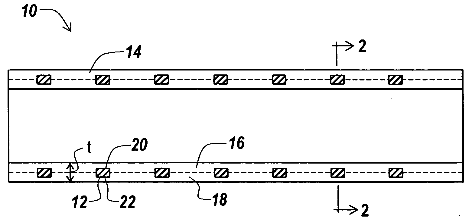
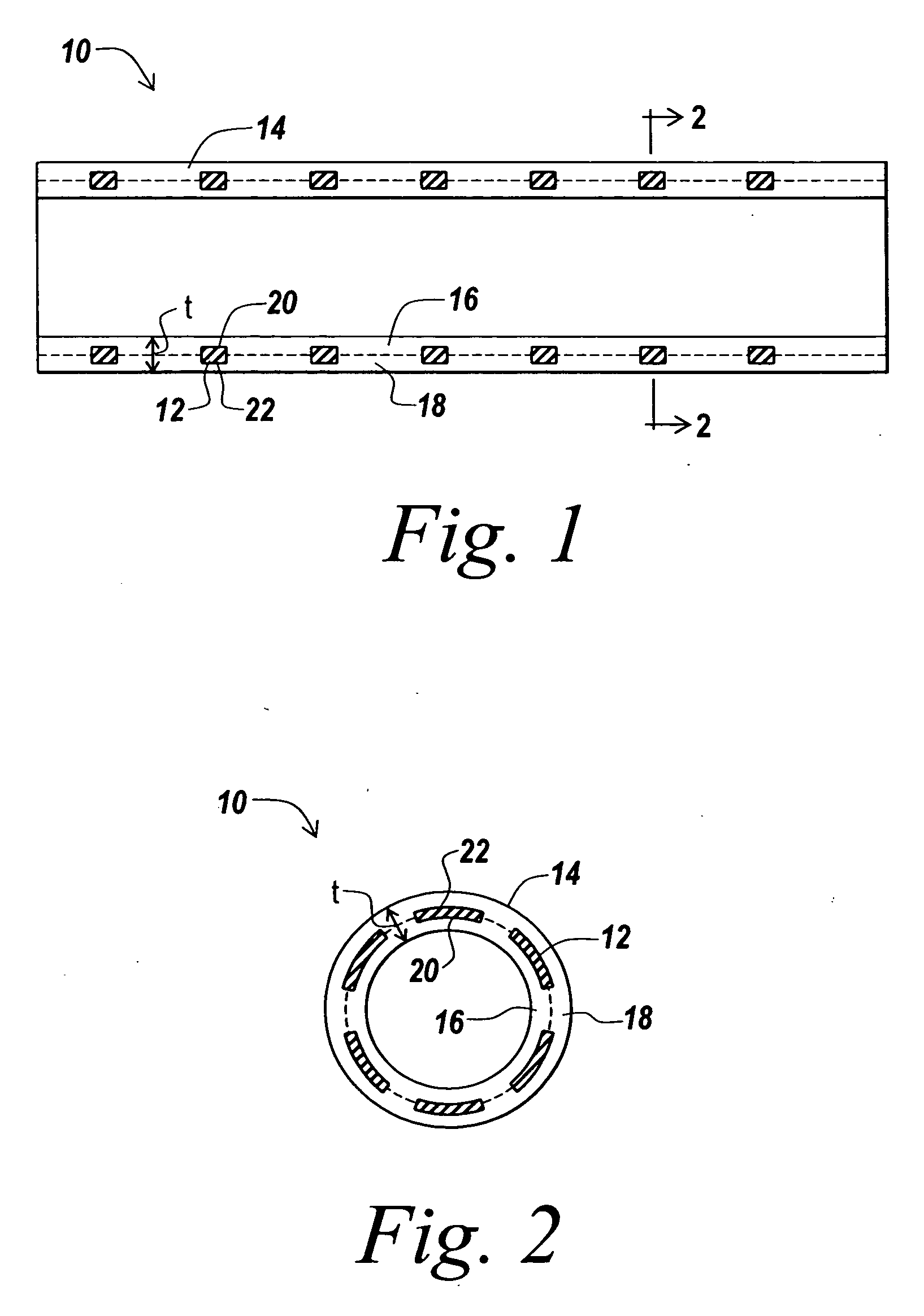
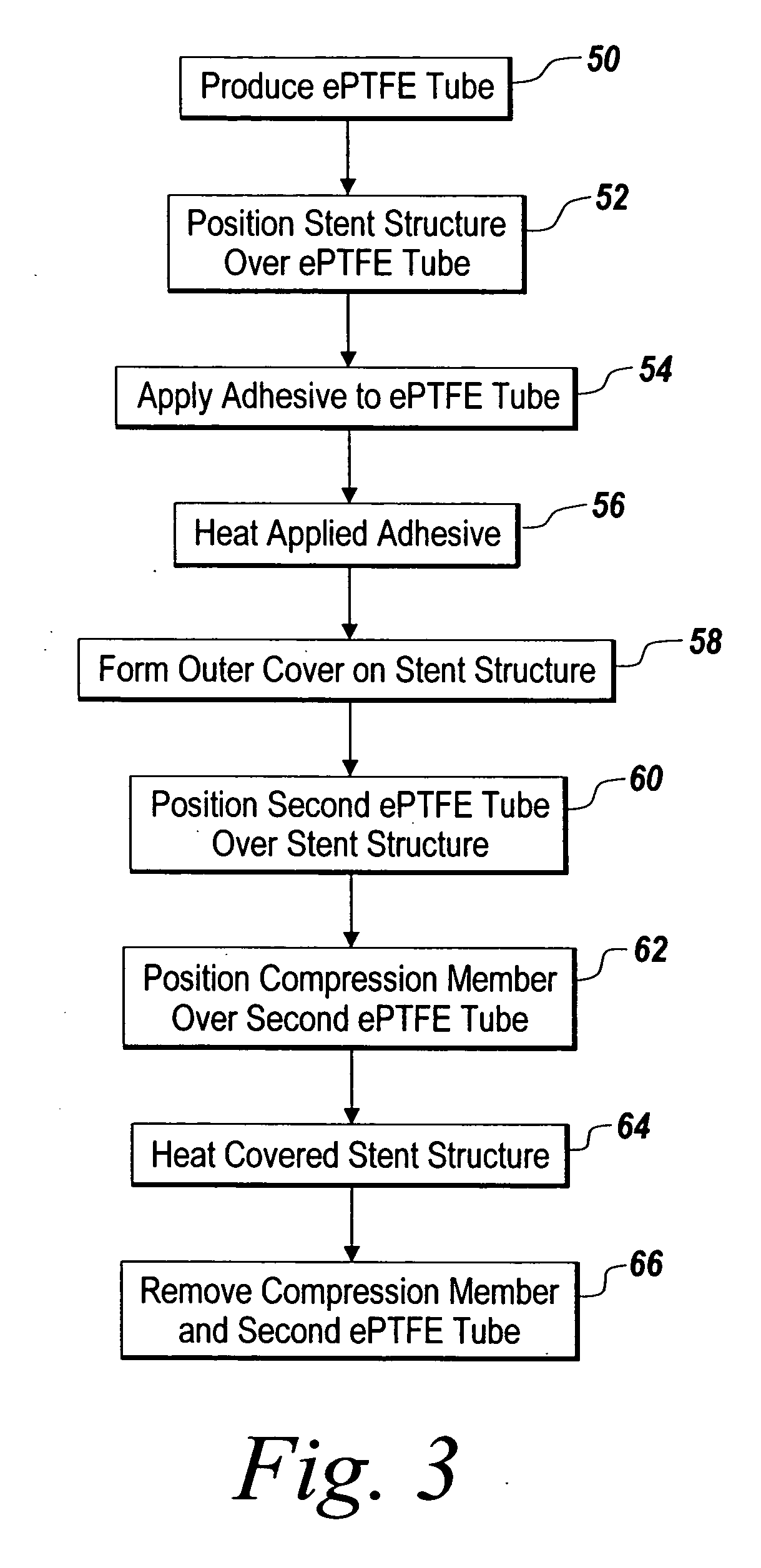
[0037] Balloon expandable PALMAZ-type slotted stents were covered with ePTFE in accordance with the method of covering a stent described above. The expanded diameter of each stent was 9 mm. Each stent included an inner cover of ePTFE and a two-layer outer cover of ePTFE as illustrated in FIG. 4 above. The inner cover of each stent was formed from an ePTFE tube that was folded over the stent structure to create the outer cover of the covered stent.

[0038] A first lot of five stents, Lot 1 in Table 1 below, were covered using an ePTFE tube having an average wall thickness 0.0073 in. and an average IND of 137 microns. A second lot of five stents, Lot 2 in Table 1 below, were covered using an ePTFE tube having an average wall thickness of 0.010 in and an average IND of 139. A third lot of four stents, Lot 3 in Table 1 below, were covered using an ePTFE tube having an average wall thickness of 0.016 in and an average IND of 147. After covering, the cover wall thickness of each stent in t...

example 2

[0041] Animal studies were conducted in which eight covered stents were deployed in the arteries of two male pigs to observe the cellular response to the stents. The stents employed were balloon expandable stents of the type described in commonly-assigned U.S. patent application Ser. No. 09 / 628,096, filed Jul. 28, 2000. The stents were covered in accordance with the method described above. A single ePTFE tube was utilized to provide the inner cover and the outer cover. The stents had expanded diameters of 6-8 mm. The ePTFE used to cover each stent had a wall thickness of 0.01 in. and an average IND of 139 microns in the unexpanded configuration.

[0042] The covered stents were deployed in the left carotid artery, the right carotid artery, the left iliac artery, and the right iliac artery of two male pigs. The covered stents were deployed with a catheter delivered PET balloon using standard operative techniques. Each stent deployed successfully at approximately 6 atm. The pigs were sa...


PUM

PropertyMeasurementUnit
Lengthaaaaaaaaaa
Pressureaaaaaaaaaa
Lengthaaaaaaaaaa

Abstract

A radially deployable covered stent that predictably and dependably expands to an increased diameter state at relatively low deployment pressures while concomitantly minimizing the risk of tearing of the stent covering during expansion. The stent covering includes an inner cover and an outer cover that are bonded together through and around the stent structure to cover the stent. The stent cover is constructed from expanded polytetrafluoroethylene (ePTFE) having a structure of nodes interconnected by fibrils. The stent covering has a radial thickness of at least about 0.008″ and an average internodal distance (IND) of at least about 100 microns when the stent is in the reduced diameter, unexpanded state. The covered stent deploys at an average deployment pressure of less than or equal to about 10 atm. A method for covering a stent structure according to the present invention includes placing a compression member in the form of a tubular sleeve over the outer cover and heating the compressed covered stent to bond the inner cover to the outer cover. An adhesive in the form of an aqueous dispersion of PTFE can be applied to either the inner cover or the outer cover to facilitate bonding of the inner cover to the outer cover.

Description

RELATED APPLICATION [0001] This application is a continuation of U.S. Pat. No. 6,808,533, which was filed on Jul. 28, 2000 and granted on Oct. 26, 2004, and which is expressly and entirely incorporated herein by reference.BACKGROUND OF THE INVENTION [0002] Radially expandable stents are commonly used to restore and maintain the patency of body passages, particularly blood vessels. Such stents are provided in a reduced diameter state suitable for percutaneous insertion into the body passage through a catheter. The stent is typically maintained in the reduced diameter state until delivery into the body passage, whereupon the stent is expanded to an increased diameter state within the body passage to hold open the body passage. A catheter delivered balloon is typically used to expand the stent to the increased diameter state. [0003] A biocompatible cover can be provided on the outer and / or inner surfaces of the stent to reduce tissue reactions associated with the expansion of the stent...

Claims


Application Information

Patent Timeline
IPC IPC(8): A61F2/86A61L31/10A61L31/14
CPCA61F2002/072A61F2210/0076A61F2/86A61F2/91A61F2220/005A61L31/10A61L31/146C08L27/18
Inventor GOODWIN, JONATHAN L.JORDAN, GARY A.GINGRAS, PETER H.
Owner ATRIUM MEDICAL
Why Eureka
Try Eureka