Synchronization of data processing units

a data processing unit and synchronization technology, applied in the field of can solve the problems of increasing wiring costs, affecting the so as to achieve accurate synchronization of data processing units and great utilization of bus transmission capacity

Inactive Publication Date: 2005-03-10
ROBERT BOSCH GMBH
View PDF3 Cites 54 Cited by
  • Summary
  • Abstract
  • Description
  • Claims
  • Application Information

AI Technical Summary

Benefits of technology

[0006] The present invention creates a method for synchronizing a plurality of data processing units in a network, which, in a simple manner and

Problems solved by technology

The expenditure for their wiring is increasing with the number of these units.
Although the use of a bus substantially reduces the wiring effort, this advantage bears the cost that the coordination in time of various sensors and/or actuators is made more difficult.
However, this solution is unsatisfactory to the extent that it requires its own signal line or a great proportion of the transmission bandwidth of a single bus line, and that counting errors, which ma

Method used


Image

  • Synchronization of data processing units
  • Synchronization of data processing units
  • Synchronization of data processing units

Examples


Embodiment Construction

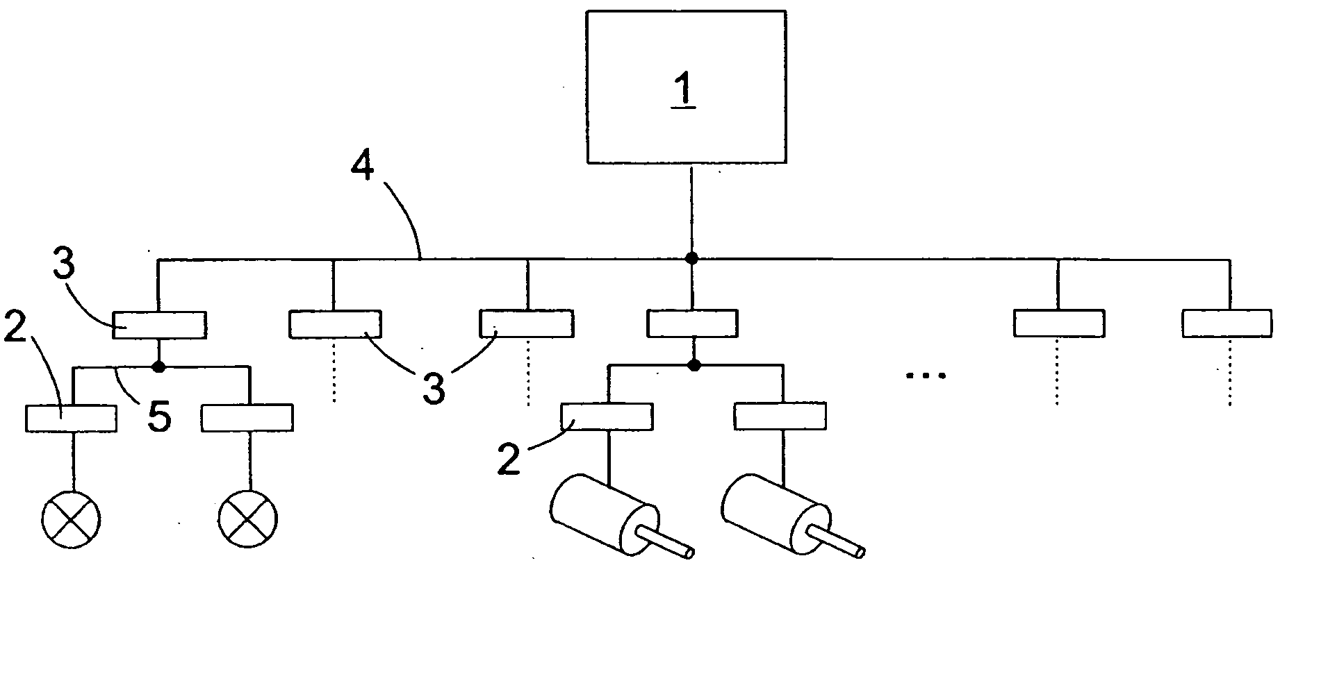
[0022]FIG. 1 is a block diagram of a hierarchically structured data processing network, in which, between a master unit and a plurality of slave units 2, a middle hierarchical plane of units 3 is inserted, which act as slaves as compared to master unit 1, and as master units as opposed to slave units 2, and shall therefore be denoted here as sub-master units 3. These communicate with master unit 1 via a CAN bus 4 and with slave units 2 via a LIN bus 5.

[0023] If, in this case, with respect to CAN bus 4, a single connected unit is designated as master unit 1, this refers only to the property that it has a local timer whose time measurement is committal for all other units 3 connected to CAN bus 4; all units 1, 3 connected to this bus are able to share control over CAN bus 4 in time division multiplex.

[0024] On a LIN bus 5, on the other hand, in each case only sub-master unit 3 is entitled to send messages on bus 5; upwards transmission of data from slave units 2 to sub-master unit 3...


PUM


Abstract

Timers of a plurality of slave units are synchronized with a timer of a master unit by a) sending a synchronization message on the first network by the master unit, which contains a time measurement of the master unit and a time scale, to the slave units; b) at each slave unit, forming the difference between a time measurement recorded in the slave unit and the time measurement received by the master unit, and correcting the current time measurement of the slave unit by this difference, and, at each unit, the recording of a time measurement upon receipt of the time scale; c) at the master unit, inserting the recorded time measurement into a subsequent synchronization message.

Description

FIELD OF THE INVENTION [0001] The present invention relates to a method for synchronizing a plurality of data processing units in a network, as well as to a network in which the method may be used. BACKGROUND INFORMATION [0002] The progressive electronification of control tasks in automotive technology has led to the application, in modern motor vehicles, of an ever growing number of electrical and electronic units, such as sensors, actuators and control units for the most various tasks. The expenditure for their wiring is increasing with the number of these units. In order to keep within limits the wiring efforts and the costs connected with them, it has proven expedient that one should no longer connect each individual sensor or each individual actuating mechanism via individual signal lines to a control unit that processes one of the sensing signals of the sensor or supplies actuating signals for the actuating mechanism, but rather that one should connect a plurality of such sens...

Claims


Application Information

Patent Timeline
IPC IPC(8): H04L12/28H04J3/06H04L7/00H04L7/02H04L12/403H04L12/413H04L12/44
CPCH04J3/0664H04L12/403H04L12/44H04L2012/40273H04L2012/40215H04L2012/40234H04L12/4625
Inventor SCHEELE, OLIVER
Owner ROBERT BOSCH GMBH
Why Eureka
Try Eureka