Stencil printing machine, ink recovering method, image unevenness preventing method, and ink adapting method

a printing machine and ink recovery technology, applied in the field of stencil printing, can solve the problems of long exposure to the atmosphere, difficulty in miniaturization, and ink quality change, and achieve the effects of preventing image unevenness, simple configuration, and recovering ink

Inactive Publication Date: 2005-03-17
RISO KAGAKU CORP
View PDF3 Cites 34 Cited by
  • Summary
  • Abstract
  • Description
  • Claims
  • Application Information

AI Technical Summary

Benefits of technology

[0017] An object of the present invention is to provide a stencil printing machine, an ink recovering method, an image une

Problems solved by technology

Consequently, when the printing is not performed for a long time, ink held in the ink pool and ink staining in the printing drum are left in a state of being exposed to the atmosphere for a long time.
This causes a problem of the ink being changed in quality.
In addition, since various rollers for supplying ink have to be arranged inside the printing drum, this causes a problem of making it difficult to miniaturize, and to reduce the weight of, the printing drum.
As a consequence, ink will not be changed in quality even when the printing is not perf

Method used


Image

  • Stencil printing machine, ink recovering method, image unevenness preventing method, and ink adapting method
  • Stencil printing machine, ink recovering method, image unevenness preventing method, and ink adapting method
  • Stencil printing machine, ink recovering method, image unevenness preventing method, and ink adapting method

Examples


Embodiment Construction

[0049] An embodiment of the present invention will be described hereinafter with reference to the accompanying drawings.

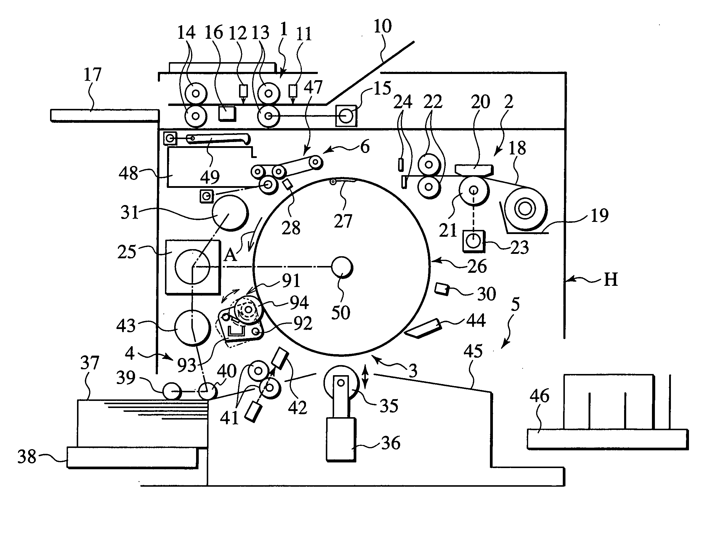
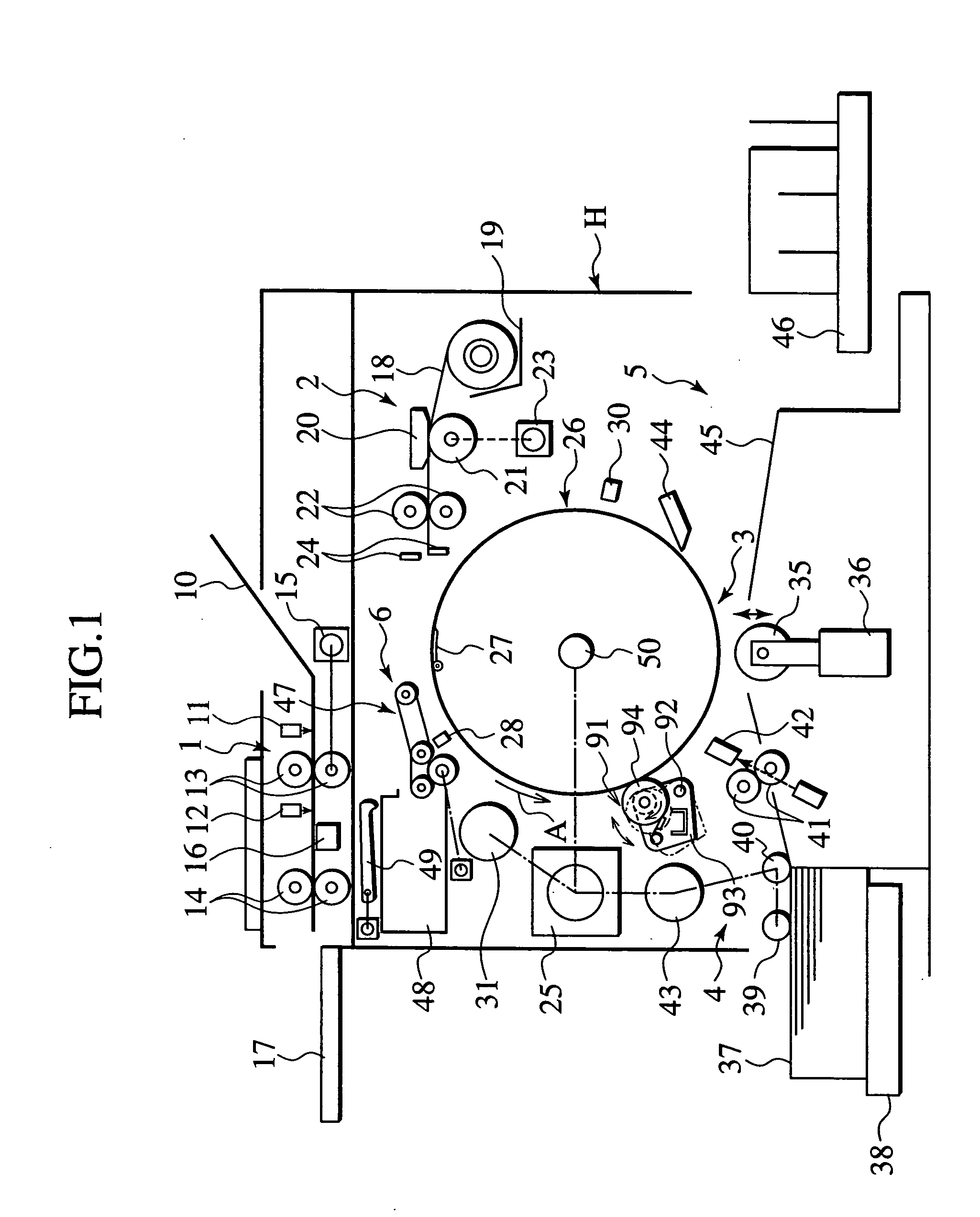
[0050] As shown in FIG. 1, a stencil printing machine is provided with an original scanning unit 1, a stencil making unit 2, a printing unit 3, a paper feeding unit 4, a paper discharging unit 5, and a stencil discharging unit 6.

[0051] The original scanning unit 1 comprises: an original setup rack 10 on which an original to be printed is loaded; original detection sensors of a reflective type 11 and 12 for checking whether or not the original is on the original setup rack 10; original leading rollers 13 and 14 for transferring the original which has been loaded on the setup rack 10; a stepping motor 15 for causing the original leading rollers 13 and 14 to be driven and rotated; an image sensor of contact type 16 for optically scanning image data of the original to be transferred by the original leading rollers 13 and 14, and for converting the image data into ele...


PUM


Abstract

A stencil printing machine has a rotatable printing drum including an outer peripheral wall of ink impermeable material. A stencil paper is mounted on the surface of the outer peripheral wall. An ink supplying mechanism includes an ink supplying unit in the outer peripheral wall of the printing drum. The ink supplying mechanism supplies ink from the ink supplying unit to the surface of the outer peripheral wall. A pressure roller presses a fed print sheet against the outer peripheral wall. An ink recovering mechanism recovers ink which has flown out of a maximum printing area of the outer peripheral wall of the printing drum. A pressing mechanism presses the stencil paper against the outer peripheral wall of the printing drum.

Description

BACKGROUND OF THE INVENTION [0001] 1. Field of the Invention [0002] The present invention relates to a stencil printing machine which transfers ink, transuding out of pores in a stencil paper, to a print medium by transferring the print medium while pressing the print medium against a printing drum on which the stencil paper is mounted; an ink recovering method; an image unevenness preventing method; and an ink adapting method. [0003] 2. Description of the Related Art [0004] As conventional stencil printing machines of this type, there have been an inner press type (disclosed in Japanese Patent Application Laid-open No. 7-132675) and an outer press type (disclosed in Japanese Patent Application Laid-open No. 2001-246828). [0005] The inner press type will be explained briefly as follows. The inner press type is provided with a printing drum and a back press roller whose diameters are nearly equal. The printing drum and the back press roller are arranged so as to be each capable of be...

Claims


Application Information

Patent Timeline
IPC IPC(8): B41L13/06B41L13/18
CPCB41L13/18B41L13/06
Inventor HASHIMOTO, HIROHIDENAITOU, TAKU
Owner RISO KAGAKU CORP
Why Eureka
Try Eureka