
Ballistic tracer platform for shotgun ammunition

a tracer platform and shotgun technology, applied in the field of shotgun ammunition, can solve the problems of difficult and time-consuming mastery, difficult game learning, and difficult to know where the shot should go relative to the target, and achieve the effect of improving the accuracy of the shooter

Inactive Publication Date: 2005-03-17
DUNNAM JAMES ALFRED +1
View PDF16 Cites 18 Cited by
  • Summary
  • Abstract
  • Description
  • Claims
  • Application Information

AI Technical Summary

Benefits of technology

[0021] The present invention provides a ballistic tracer platform for a tracer projectile which, when loaded into a shotgun shell, can be used to provide a shooter with a consistent reference, allowing him or her to make appropriate corrections to his or her shooting technique. This invention serves as a training aid to improve a shooter's accuracy for shotgun sports such as Trap, Skeet, or Sporting Clays. It also serves as a shotgun aiming and training aid for hunters, as well as having combat applications for military and police personnel. The invention enables the shooter to visualize the shot with respect to the target by firing the tracer ammunition in a manner identical to that of standard ammunition. The invention described herein can be modified and adjusted for use with all shot types, and it can be used in all shotgun gauges, including 4, 8, 10, 12, 16, 20, 28, and 410, in both single and double barrel shotguns.

Problems solved by technology

The supersonic nature of the shot, with speeds ranging from approximately 1100 to 1400 ft / s (335 to 427 m / s), and the speed of the target, ranging from approximately 40 to 70 miles / h (64 to 112 Km / h), make it almost impossible for the shooter to know where his shot should go relative to the target.
This makes the game a real challenge to learn, and very difficult and time-consuming to master.
Ignition type inventions although promising have had very limited success in the market place, these include:
The marginal success of these inventions can be attributed to the high price charged and the clear fact that these inventions do not function properly.
Currently available tracers, while visible, do not provide the shooter with a consistent reference to improve his or her shooting.
(a) The tracer does not have a flight pattern consistent with that of the shot and therefore fails to provide the shooter with an appropriate reference.
(b) The tracer fails to ignite consistently because the pyrotechnic material does not have enough time and surface area to absorb heat from the propellant blast as it separates from the shot cup.
More specifically, currently available tracers fail because the tracer projectile travels randomly with the shot pattern.
The inaccuracy of current tracer designs stems from the fact that the tracer projectile is located at the bottom of the shot cup.
These interferences present the greatest challenge in designing an effective shotgun tracer.

Method used


Image

  • Ballistic tracer platform for shotgun ammunition
  • Ballistic tracer platform for shotgun ammunition
  • Ballistic tracer platform for shotgun ammunition

Examples


Embodiment Construction

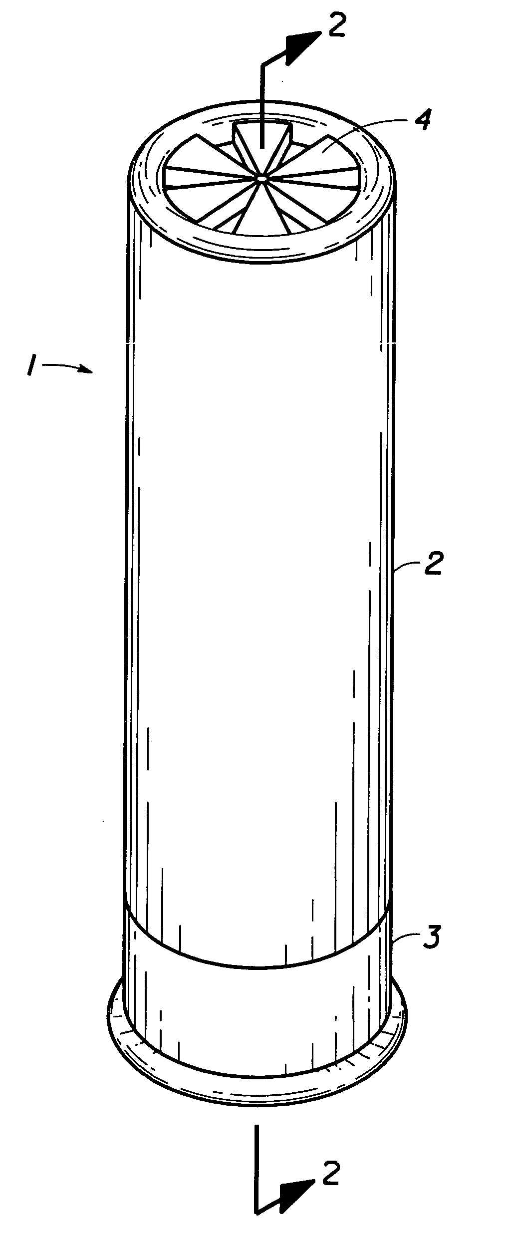
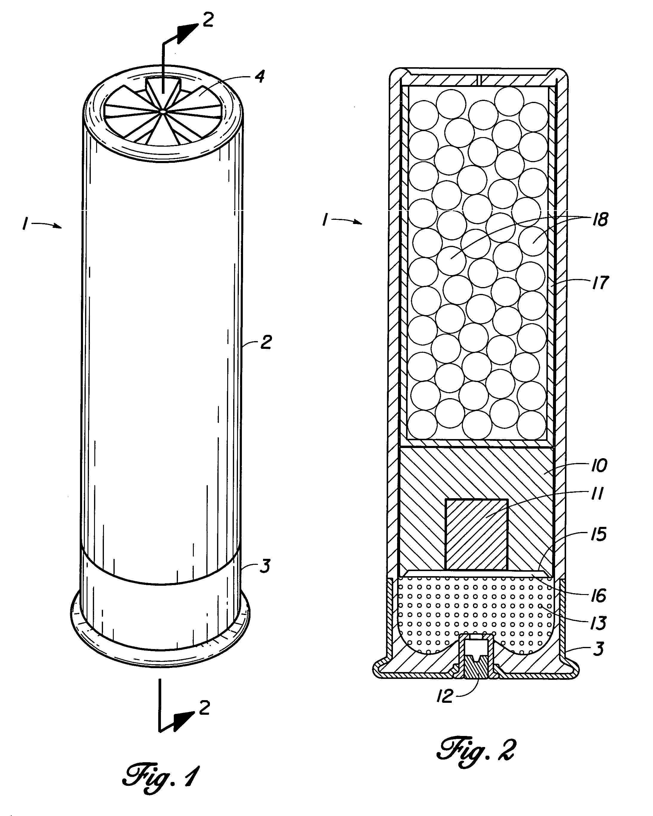
[0040] The present invention is designed to be used with a typical shotgun shell 1, which generally has a hull 2 with a metal base cap 3 and a crimped top 4.

[0041] The sectional view in FIG. 2 shows a shotgun shell 1 which has been assembled with the cylindrical ballistic tracer platform 10 holding the tracer element 11 within its coaxial cylindrical cavity. Inside the base cap 3 is the primer 12, which ignites the propellant 13 contained in the bottom end of the shotgun shell 1. The bottom 15 of the ballistic tracer platform 10 is formed to create a gas seal cavity 16 between the ballistic tracer platform 10 and the propellant 13, allowing the gases to expand and the pyrotechnic mixture contained in the tracer element 11 to ignite. Above the ballistic tracer platform 10 is the shot cup 17 (or shot holder), which has been filled with shot pellets 18.

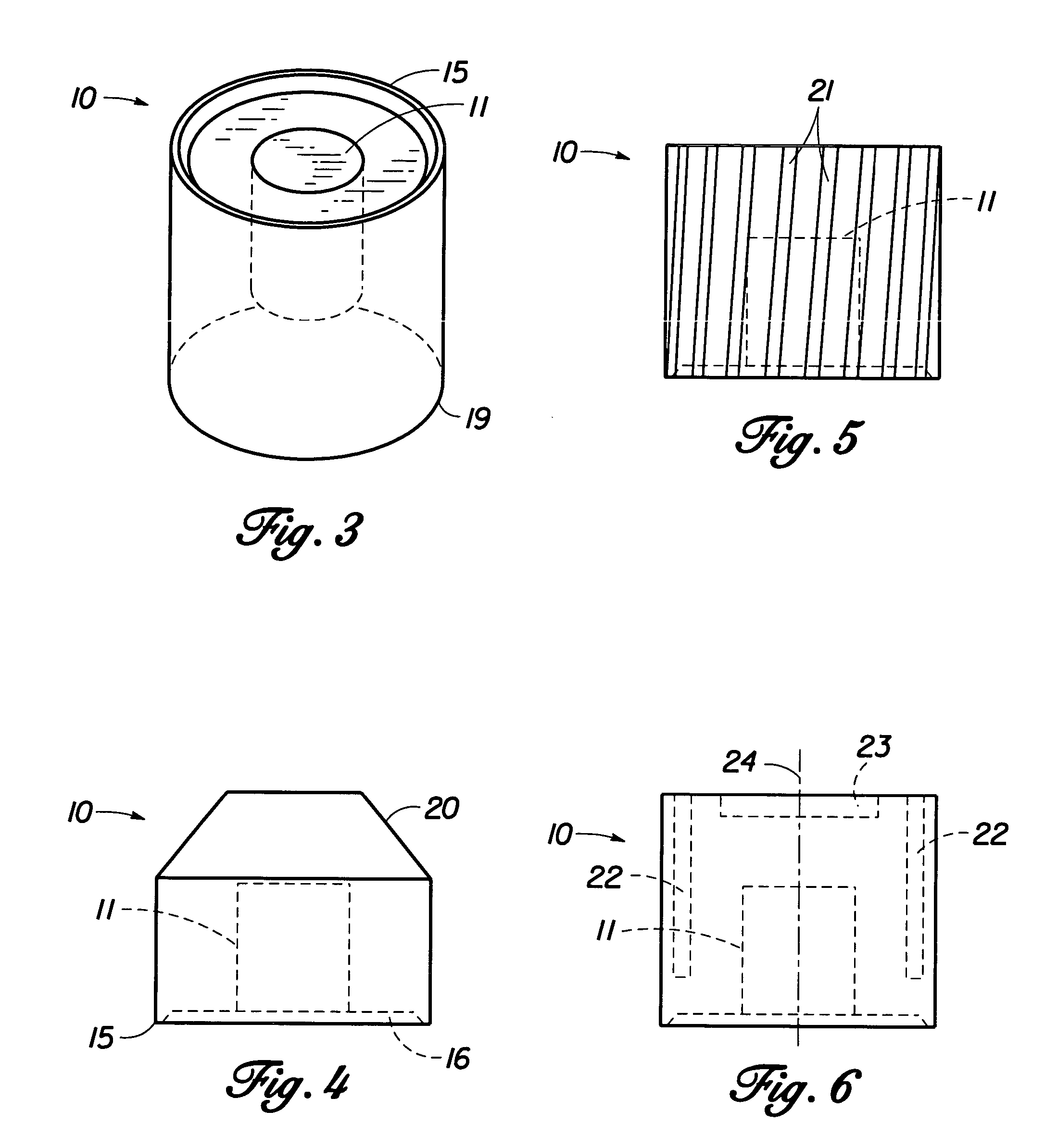
[0042]FIG. 3 shows a typical cylindrical ballistic tracer platform 10 holding the tracer element 11 in its cylindrical coaxial cavity...


PUM


Abstract

A ballistic tracer platform for use with a shotgun shell to provide an aiming and training aid for shotgun shooting sports, which also can be used for military and police applications. The ballistic tracer platform carries a tracer element, which provides the shooter with a consistent reference to make corrections to his or her aiming point and shooting techniques. The ballistic tracer platform can be used in ordinary shotgun shells. The ballistic tracer platform consists of a cylindrical structure with a coaxial cylindrical cavity in which the tracer element is disposed. The tracer element can be composed of incendiary or non-incendiary materials. The ballistic tracer platform can be modified to improve its ballistic shape, such as modifying the shape of its nose. Mass can be added to cavities formed in the ballistic tracer platform in order to adjust the weight of the device. Grooves, fins, or orifices can be formed in surface of the device to create additional spin.

Description

FIELD OF THE INVENTION [0001] The present invention relates to shotgun ammunition, more specifically tracers used to make the shot visible to shooters. BACKGROUND OF THE INVENTION [0002] Shotgun sports date back to the late 1700's with the introduction of trap shooting of live pigeons. The sport later evolved with the introduction of clay pigeons in 1880 and the development of reliable clay throwing machines in 1890. The two main types of shotgunning games that evolved are Trap and Skeet. Trap is a game where the clays are thrown from a single location or house, at different random angles while the shooters rotate between five shooting positions. Skeet is a game where clays are thrown from two locations or houses, at consistent trajectories while shooters rotate between eight stations. International trap was introduced as an Olympic Sport in 1952, while International Skeet was introduced as an Olympic Sport in 1968. In Sporting Clays, a third shotgunning game which has been introduc...

Claims


Application Information

Patent Timeline
Patent Type & Authority Applications(United States)
IPC IPC(8): F42B7/08F42B12/38
CPCF42B12/38F42B7/08
Inventor DUNNAM, JAMES ALFREDQUINTANA, MAURICIO F.
Owner DUNNAM JAMES ALFRED
Learn More