
Brake disk for vehicles

a technology for brake pads and vehicles, applied in the field of brake systems, to achieve the effect of optimizing the wear and tear of the brake pads, improving heat dissipation, and improving cooling

Inactive Publication Date: 2005-03-17
BRAKING ITALA
View PDF9 Cites 39 Cited by
  • Summary
  • Abstract
  • Description
  • Claims
  • Application Information

AI Technical Summary

Benefits of technology

[0015] An advantage of the present invention is that the alternating protruding and indented segments provide for improved heat dissipation and better cooling than continuous surface constructions.
[0016] Another advantage of the present invention is that the irregularly shaped protruding segments balance and optimize wear on the brake pads, thus extending the life thereof.
[0017] A further advantage of the present invention is that the indented segments provide that portions of the brake pads are not in frictional contact with the brake disk during braking, thus permitting cooling of the pads as well as the disk.
[0018] Another advantage of the present invention is that the alternating protruding and indented segments facilitate rapid changes of the specific pressure applied by the pad on the disk, thus providing better initial grip than other disk designs.
[0019] Yet another advantage of the invention is that the variegated surface facilitates beading of the brake pad surface during use, thus helping to prevent material crystallization and extending pad life.
[0020] Still another advantage of the invention is that there are no holes or apertures extending all the way through the disk, thus minimizing the potential for capturing impediments, such as twigs or other debris which might interfere with the operation of the brake systems.

Problems solved by technology

Significant challenges in braking systems and disk brakes in particular deal with overheating and loss of friction, since the energy absorption associated with braking generates a significant amount of heat energy.

Method used


Image

  • Brake disk for vehicles
  • Brake disk for vehicles
  • Brake disk for vehicles

Examples


Embodiment Construction

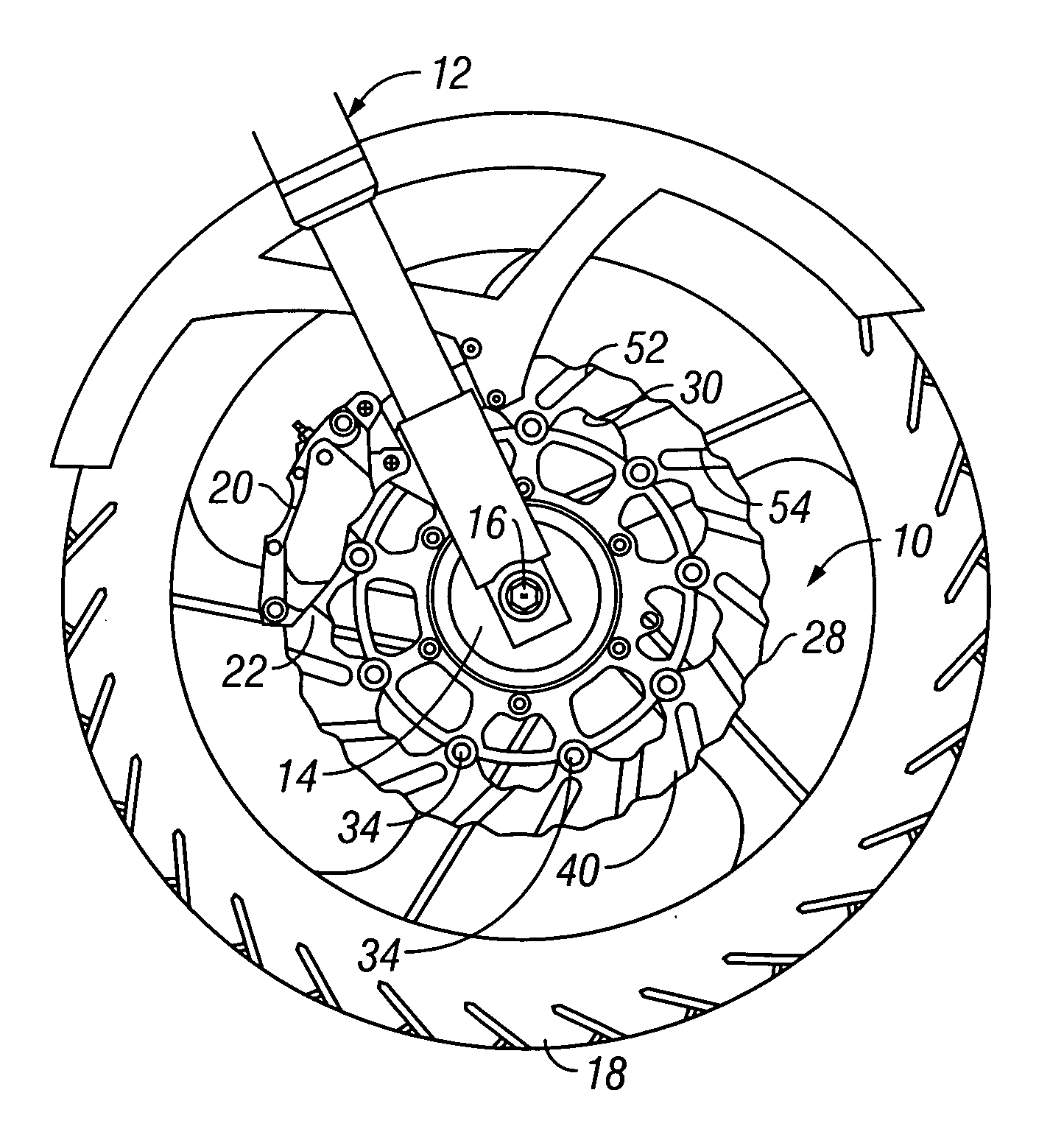
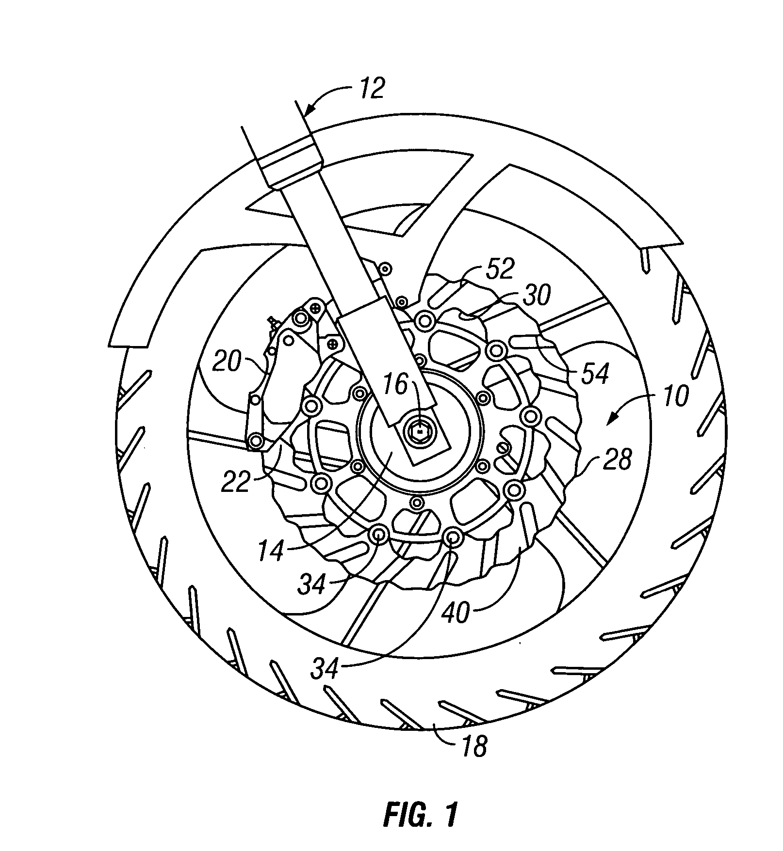
[0033] A preferred embodiment of the present invention is a brake disk device adapted for use on a vehicle, particularly with motorcycles, motor driven cycles and bicycles having disk type brakes. A preferred embodiment of the invention is illustrated in the several figures of the drawing and is identified by the general reference character 10.

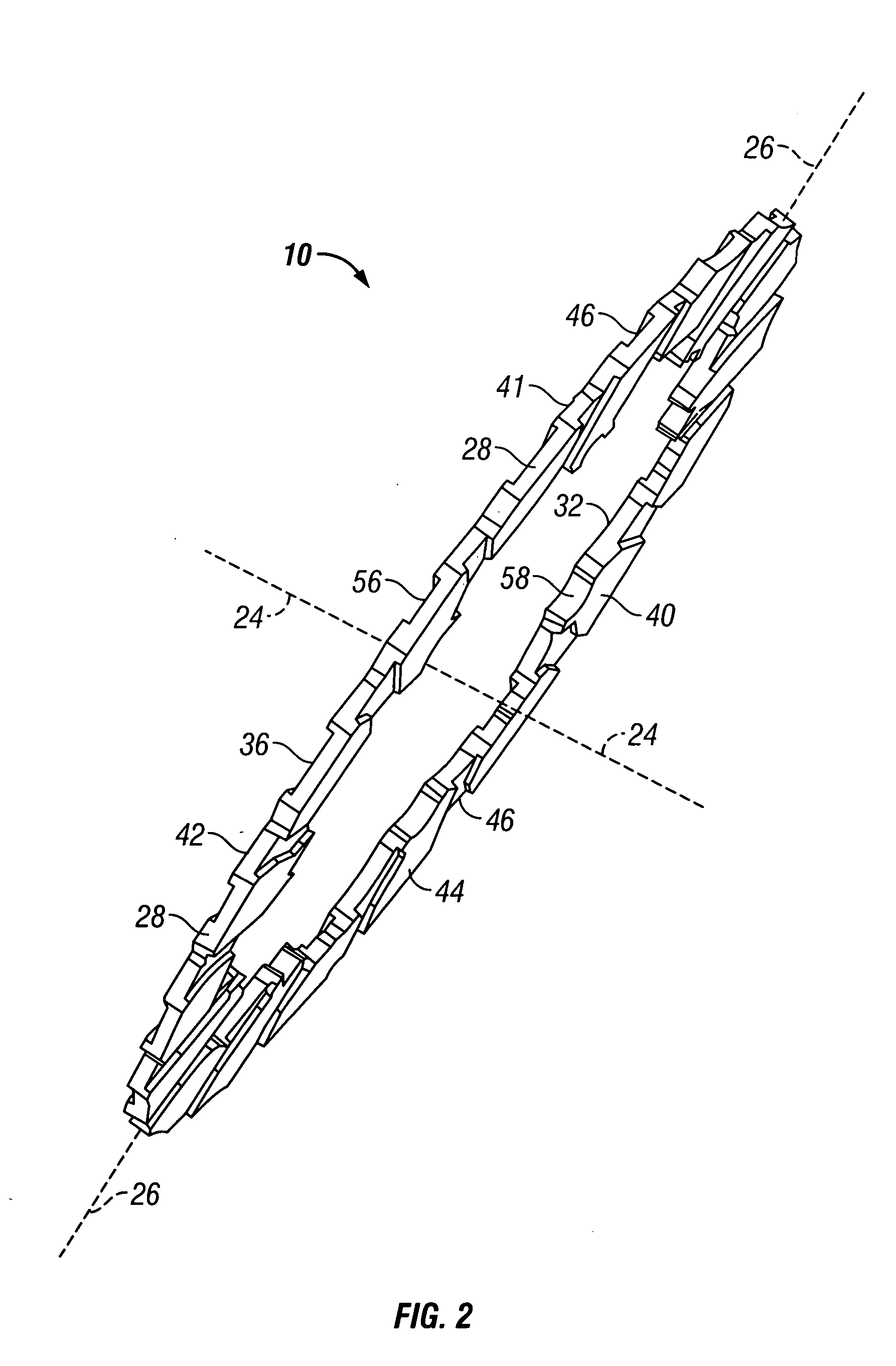
[0034] A preferred brake disk 10 is illustrated in FIG. 1 as being installed on a vehicle 12 (partially shown). Other views of the preferred embodiment 10 are illustrated in FIGS. 2, 3 and 4 of the drawings, and the present description refers to all of these figures. The vehicle 12 will typically be a motorcycle, although other vehicles and transrotary mechanisms upon which disk brakes are utilized could also benefit from the invention. The perspective view of FIG. 1 shows the disk 10 mounted on a hub 14 of an axle 16 of a wheel 18. The remainder of a conventional disk brake mechanism, including calipers 20 including brake pads 22, is illustr...


PUM


Abstract

An brake disk (10) is provided for use in installation on vehicles (12) or transrotary systems for use in conjunction with brake pads (22). The disk (10) includes an obverse side (40) and a reverse side (42) each of which is provided with a series of alternating protruding segments (44) and indented segments (46). The indented segments (46) on one side of the disk (10) are situated axially opposite protruding segments (44) on the other side. Each protruding segment (44) includes a leading edge (52) for engaging the brake pads (22). The particular shapes and relative circumferential widths of the alternating segments vary depending on particular usage.

Description

TECHNICAL FIELD [0001] The present invention relates generally to vehicular transportation and more particularly to brake systems using brake disk devices. BACKGROUND ART [0002] Any moving vehicle, or any item with transrotary movement, needs some sort of mechanism for absorbing energy, in order to reduce the speed of rotation. One of the most common and most effective methods for braking on vehicles in the disk brake system. This style uses a disk which is coupled to and rotates with the wheel and brake pads which are fixed in position and frictionally engage the sides of the disk when activated. This style of brake mechanism is used on many types of vehicles, but is particularly popular on motorcycles. [0003] The earliest and simplest forms of disk brakes utilize simple flat disks having smooth surfaces and regular shapes. However, as performance requirements became more rigorous various modifications have been introduced. Improvements have been particularly aimed at improving the...

Claims


Application Information

Patent Timeline
IPC IPC(8): F16D65/12F16D69/00
CPCF16D65/12F16D2065/026F16D2065/1332F16D2200/0039F16D2200/0013F16D2200/003F16D2069/004
Inventor GREPPI, BRUNO
Owner BRAKING ITALA
Learn More