Particle accelerator space engine

a technology of space engine and accelerator, which is applied in the direction of machines/engines, cosmonautic vehicles, transportation and packaging, etc., can solve the problem of high rotational velocity

Inactive Publication Date: 2005-03-17
FOSTER JOHN P
View PDF5 Cites 8 Cited by
  • Summary
  • Abstract
  • Description
  • Claims
  • Application Information

AI Technical Summary

Problems solved by technology

That experiment proved controversial, with problems arising due to small test values of acceleration change, that required extremely high rotational velocities.

Method used


Image

  • Particle accelerator space engine
  • Particle accelerator space engine
  • Particle accelerator space engine

Examples


Embodiment Construction

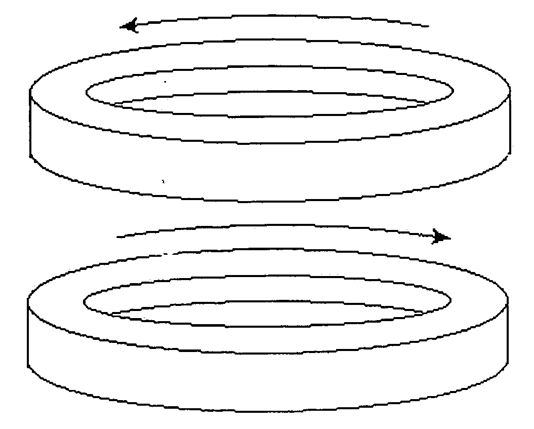
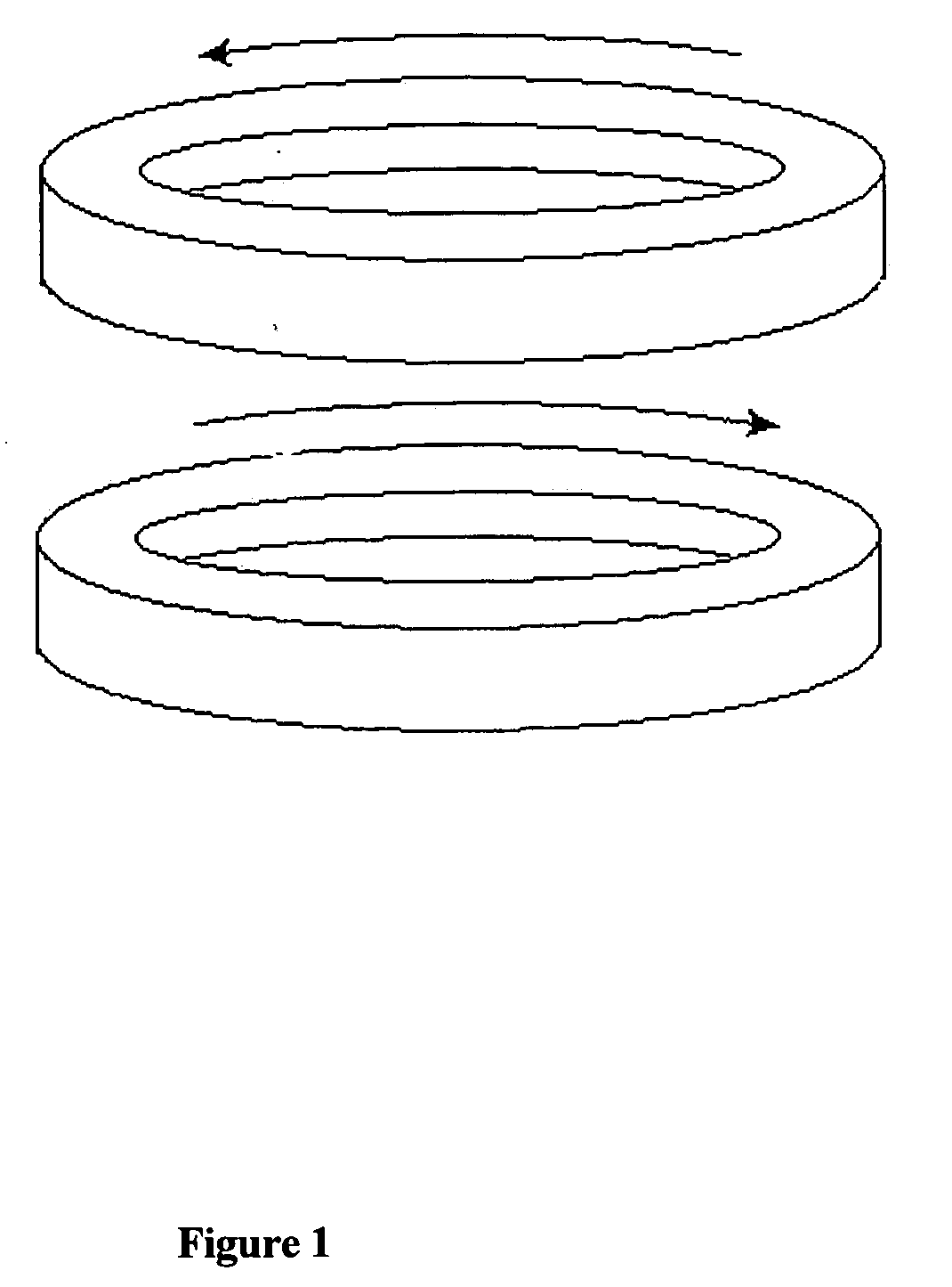
[0006] Referring now to the drawings; The Particle Accelerator Space Engine is composed of two circular particle accelerator / storage ring / braking devices, mounted one above the other, with particle streams traveling in counter-rotational directions, as depicted in FIG. 1. The configuration is for the purpose of stabilizing cabin motion, to prevent the cabin from rotating. Both clockwise, and counterclockwise particle accelerators may produce horizontal and / or vertical propulsion. but are capable of providing each other with equal but opposite recoil acceleration. The determination of function at a given time as a particle accelerator, storage ring, or braking device is regulated by particle stream velocity at a given time. The ability to kick a particle to a higher, stable, or lower velocity is regulated by timing and intensity of particle accelerator station kicks, and magnetic forces located about the circumference of the doughnuts. Although these technologies are common practice ...


PUM


Abstract

The invention provides two methods of propulsion for vertical and horizontal aerospace flight. Both methods manipulate the mass of a moving particle stream to achieve a desired result. In vertical propulsion, the invention circulates matter, within the confine of a machine, such that a portion of particle speed, which is perpendicular to gravity, is greater than the magnitude of velocity required for circular orbit of the planet, so as to develop radial acceleration relative to the planet center, creating a vertical force, associated with the mass of the particle stream times the radial acceleration, thereby generating vertical thrust. This methodology shall be referred to as “Gyroscopic Lift”. This invention also provides an additional method of horizontal propulsion. In horizontal propulsion, the invention may alternate acceleration and deceleration of matter, as it travels in a circulatory system, so as to create changing centripetal acceleration, and a directional imbalance of forces, thereby developing an outlet to be employed in horizontal thrust. As particles accelerate to the rear during the first ½ cycle an opposite but equal reaction causes forward horizontal propulsion. As particles decelerate in the 2nd ½ cycle, the opposition to slowing down causes forward horizontal propulsion. On port and starboard sides, forces causing particle stream acceleration or deceleration are balanced so as to cancel each others effect. This method of alternating acceleration and deceleration shall be referred to as “Impulse Propulsion”. Although the particular embodiment shown utilizes particles traveling perpendicular to gravity, it should not be concluded that this is the only arrangement possible. Whenever a particle has a component of velocity perpendicular to gravity in excess of circular orbit velocity, it is suitable to provide some measure of vertical thrust. Thus many particle accelerator designs utilizing this feature are feasible for the present invention. As an example, a particle accelerator whose axis of rotation is not aligned with the z axis should provide vertical lift and possibly other precession types of motion for a vehicle. As an alterative embodiment of this invention it provides some measure of gyroscopic lift that may be harnessed. Another example; If the circulatory path of the doughnut is comprised of a shape other than a circle it may increase the potential effect of impulse propulsion, but reduce gyroscopic lift efficiency. A shape comprised of two half circle accelerators, linked into a circulatory pattern by two parallel linear accelerators, would increase the potential horizontal thrust of impulse propulsion. Such is an alternative embodiment of this invention. Thus the invention embraces all space engines which utilize the principles of Gyroscopic Lift, or Impulse Propulsion. Obviously, many modifications and variations of the present invention are possible in the light of the above teachings. It is therefore to be understood that within the scope of the appended claims, the invention may be practiced other than as specifically described.

Description

CROSS REFERENCE TO RELATED APPLICATIONS [0001] This invention pertains to a propulsion device employing particle accelerator / storage ring / braking device technology to provide novel method and mechanism for vertical propulsion, referred to as “Gyroscopic Lift”. The invention also utilizes particle accelerator / storage ring / braking device in secondary method for horizontal propulsion relative to the ship, referred to as “Impulse Propulsion”. FEDERAL STATUS OF FUNDING [0002] The invention described herein is not a Federal funded research and development project. BACKGROUND OF INVENTION [0003] The invention builds upon principles found in experimentation by Hideo Hayasaka and Sakae Takeuchi at Tohoku University, Japan, as published in 1989. In this experiment, high speed gyroscopes were allowed to fall between two laser beams inside a vacuum chamber for the purpose of measuring the rate of fall. The conclusion was that the high speed gyroscope fell at a lesser rate of acceleration than g...

Claims


Application Information

Patent Timeline
Patent Type & Authority Applications(United States)
IPC IPC(8): B64G1/40F03H99/00
CPCF03H99/00B64G1/409
Inventor FOSTER, JOHN P.
Owner FOSTER JOHN P
Why Eureka
Try Eureka