Operating apparatus for game machine

a game machine and operating apparatus technology, applied in the field of game machines, can solve the problems of difficulty in operation, high load per unit area, high cost of the device itself, etc., and achieve the effects of improving operation ability, low load, and simple structur

Active Publication Date: 2005-03-17
NINTENDO CO LTD +1
View PDF7 Cites 37 Cited by
  • Summary
  • Abstract
  • Description
  • Claims
  • Application Information

AI Technical Summary

Benefits of technology

[0013] According to an illustrative embodiment, it is possible to prevent the depressing members from being upwardly actuated by the engaging protrusions, and therefore, even if the operator beats any place of the operation input portion, the depressing protrusions assuredly depresses the elastic member, capable of outputting the same operation signal. Therefore, it is possible to improve operational abilities. Furthermore, the depressing members are supported by only the elastic members, which makes it possible to operate with a relatively low load.
[0014] In one aspect of an illustrative embodiment, an operating apparatus for a game machine, further comprising: a cable that is connected to the inside of the housing at one end and has a connector to be connected to the game machine at other end; a first housing concave portion formed on the other main surface of the housing and houses the cable and the connector, wherein the first housing concave portion is provided with a plurality of pinch protrusions for pinching both sides of the cable at a position where the cable is housed. More specifically, the operating apparatus for game machine (10) is connected to the game machine (100) by the cable (38). The cable (38) is connected to the inside of the housing (14 or 16; the third housing 18 in this embodiment) at the one end and has a connector (36) to be connected to the game machine (100) at the other end. On the other main surface (124) of each of the housings (14, 16), the first housing concave portion (124a) for housing the cable (38) and the connector (36) is provided. The first housing concave portion (124a) is provided with the plurality of pinch protrusions (124b) for pinching the both sides of the cable (38) at the position where the cable (38) is housed. Thus, the first housing concave portion is provided with the pinch protrusions for pinching both sides of the cable so that it is possible to prevent the cable from being disengaged and capable of housing and holding the cable and the connector with a simple structure. Furthermore, it is possible to reduce the size of the apparatus itself when it is stored.
[0015] In one illustrative embodiment, the plurality of pinch protrusions are formed in such a manner as to be shifted from each other on both side surfaces of the first housing concave portion. More specifically, the plurality of pinch protrusions (124b) are formed in such a manner as to be shifted from each other on both side surfaces of the first housing concave portion (124a). Accordingly, the cable (38) is held as if it snakes by the plurality of pinch protrusions (124b). Thus, by the restoring force of the cable to the normal state, the cable and the connector are sure to be held. This allows the operating apparatus for a game machine to be easily portable.
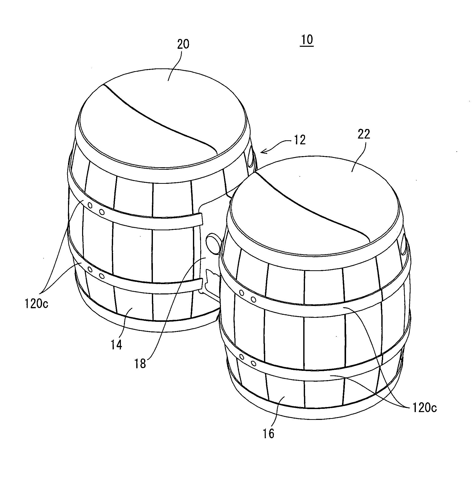
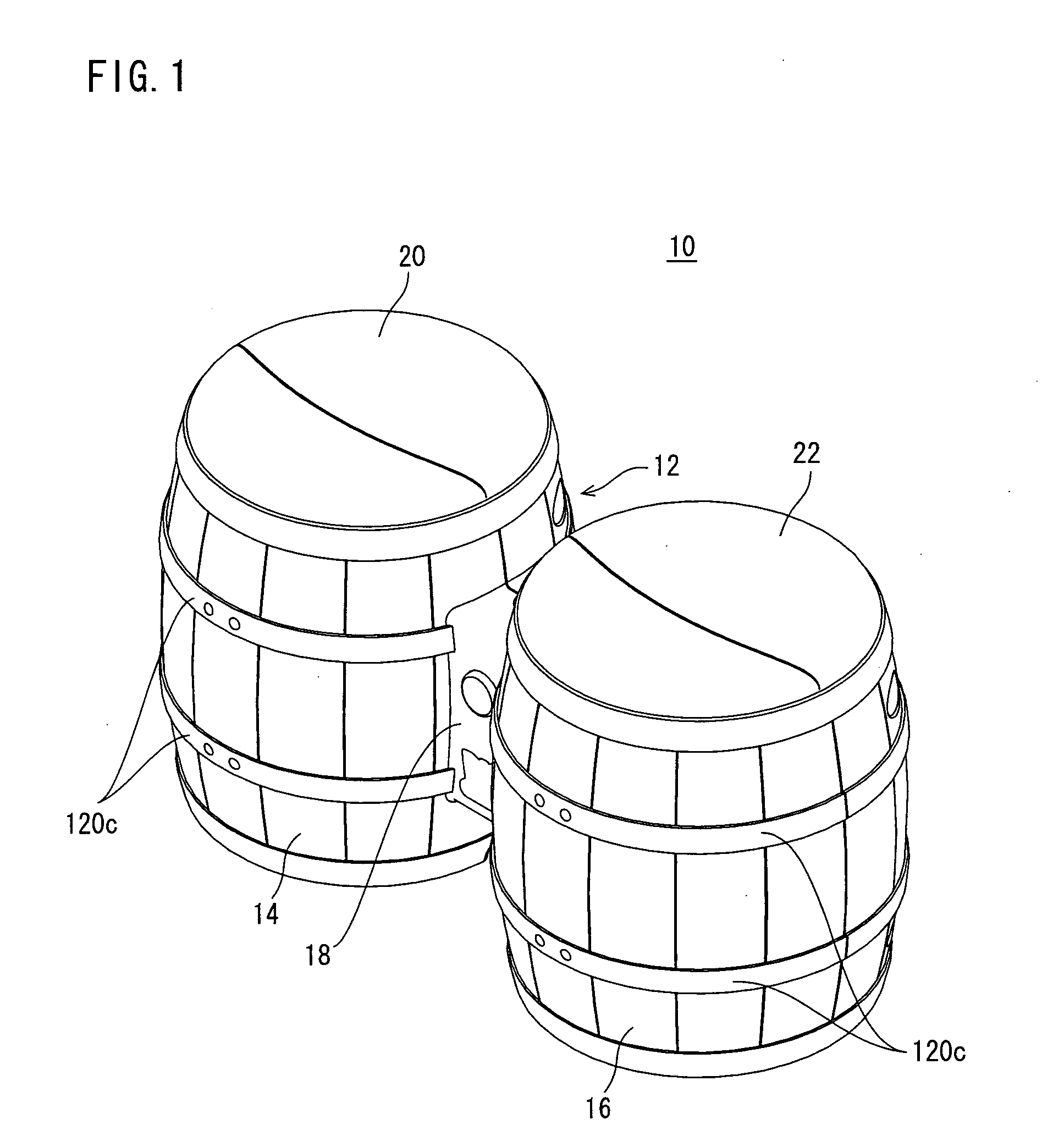
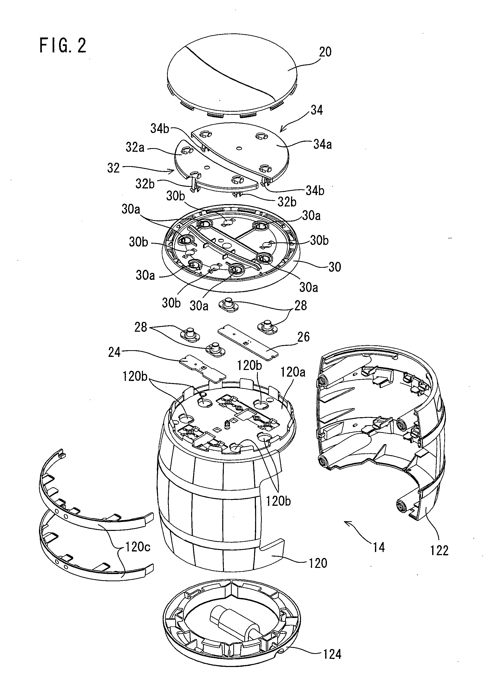
[0016] In another illustrative embodiment, an operating apparatus for a game machine, wherein, the operation input portion has a first operation input portion and a second operation input portion, the housing includes a first housing provided with the first operation input portion, and a second housing provided with the second operation input portion and having approximately the same size as the first housing, and a third housing to be coupled with the first housing and the second housing and being smaller than the first housing and the second housing, wherein the first housing concave portion is formed on at least one of the first housing and the second housing, the second housing concave portion is formed due to a difference between a size of the first housing and the second housing and a size of the third housing, the cable extends from the third housing, the cable is wrapped around the third housing so as to be housed within the second housing concave portion, the connector and a part of the cable are fitted into the first concave portion, and whereby, the cable and the connector are housed and held. More specifically, the operation input portion (20, 22) includes the first operation input portion (20) and the second operation input portion (22). The housing (14, 16, 18) consists of the first housing (14), the second housing (16), and the third housing (18). The first housing (14) is provided with the first operation input portion (20). The second housing (16) has approximately the same size (shape) as the first housing (14), and the second housing (16) is provided with the second operation input portion (22). The third housing (18) couples the first housing (14) and the second housing (16), and is smaller than them. The difference in size provides the second concave portion, that is, a narrow part (128) to the operating apparatus for a game machine (10), and the cable (38) extends from the third housing (18). Accordingly, the cable (38) is wrapped around the third housing (18) so as to be housed within the second housing concave portion (128), and then, the connector (36) and a part of the cable (38) are fitted into the first housing concave portion (124a), and whereby, the cable (38) and the connector (36) are housed and held. Thus, the cable is wrapped around the second housing concave portion, and part of the cable and the connector are fitted into the first housing concave portion. Therefore, this makes it possible to prevent the cable and the connector from being disengaged from the housing, so the cable and connector are capable of being effectively housed.

Problems solved by technology

However, in the above-described input device for a game machine, the pressure sensor and the vibration sensor are provided to each of the plurality of input areas, and therefore, the device itself is expensive.
However, a problem occurs when a membrane switch is applied.
A relatively high load needs to be applied per unit area, causing a difficulty in operation when playing the game.
In the above-described PC-card-shaped input device for game, a problem still remains.
If the PC card is also carried together with the notebook computer in addition to the PC-card-shaped input device for game, the PC-card-shaped input device for game cannot be housed within the card slot, and cannot be put in a computer bag because it is bulky.
In such a case, further problems occur because the PC-card-shaped input device has to be carried separately, therefore, the cable can become disengage due to the weight of the connector, making transportation difficult.
In the above-described electronic equipment, due to the space required for forming the snaking groove, the housing increases in size, causing a problem.
Another problem is that if the bending radius of the snaking groove is set to an optimum value, the cable is easily disengaged, or the cable is easily broken due to an excessive load (stress), causing difficulties with the equipment's practicality.

Method used


Image

  • Operating apparatus for game machine
  • Operating apparatus for game machine
  • Operating apparatus for game machine

Examples


first embodiment

[0064] As shown in FIG. 6 and FIG. 7, in the first embodiment, the housing concave portion 124a is provided at the bottom surface panels 124 of both housings 14, 16. Alternatively, the housing concave portion 124a is provided at the bottom surface panel 124 of the only one housing.

[0065] Accordingly, when the operating apparatus 10 is not used, the cable 38 is wrapped around the narrow part 128, that is, the third housing 18, and a part of the cable 38 and the plug 36 can be housed within the housing concave portion 124a as shown in FIG. 7. At this time, a part of the cable 38 is pinched by the pinch protrusions 124b as if it snakes, so that a force to restore to an original shape of the cable 38 works to hold the cable 38 in place. This makes it possible to prevent the part of the cable 38 and the plug 36 from being disengaged from the housing concave portion 124a. That is, it is possible to house the cable with a simple structure. Thus, the plug 36 and the cable 38 are housed and ...

second embodiment

[0098] Accordingly, in the second embodiment, as shown in FIG. 12, a connecting cable 40 having connectors that are detachably connected to the respective connectors 16a and 18a is utilized. It is noted that although a description of a detailed shape of the connectors provided to the connecting cable 40 is omitted, it is appropriate that connectors having the same shape as the connectors 16a and 18a are used. Thus, by indirectly connecting the second housing 16 and the third housing 18 with use of the connecting cable 40, the third button 56 and the fourth button 58 are electrically connected to the controller IC 50.

[0099] It is noted that although in the second embodiment, the second housing 16 and the third housing 18 are electrically connected by use of the cable, there is no need to be restricted thereto. That is, another method such as connecting via an electromagnetic wave (for example, electric wave or infrared rays) in a wireless manner may be applied.

[0100] Although not il...


PUM


Abstract

An operating apparatus for game machine includes a depressing member, and a main body of the depressing member is provided with three engaging protrusions and two depressing protrusions that downwardly protrude. For example, the two depressing protrusions are provided between the three engaging protrusions. In response to a beating operation by a player, the right side of the depressing member is depressed, and then, an engaging portion of the engaging protrusion at the left side is engaged with a rear surface of an upper surface panel. Accordingly, the depressing member is sure to be depressed at the right side without being upwardly actuated, and a rubber switch depressed by the depressing protrusion is brought into contact with a board. At this time, a contact provided on the board and a contact provided on the rubber switch are brought into contact with each other, and an operation signal according to the beating operation is output to the game machine.

Description

FIELD OF THE INVENTION [0001] The present invention relates to operating apparatus for game machines. More specifically, the present invention relates to an operating apparatus for a game machine that outputs an operation signal to a game machine in response to a beating (i.e., percussion) operation by an operator. BACKGROUND AND SUMMARY OF THE INVENTION [0002] An example of this kind of a conventional operating apparatus for a game machine is disclosed in Japanese Patent Laying-open No. 2001-276421 [A63F 13 / 00, A63F 13 / 06, G10H 1 / 34, H01H 13 / 18] laid-open on Oct. 9, 2001. The input device for a game machine is provided with a plurality of input areas each of which has a pressure sensor and a vibration sensor. Then, when the input area is beaten, a different sound for each input area is generated. [0003] Another example of this kind of an operating apparatus for a game machine is disclosed in Japanese Patent Laying-open No. 2000-157736 [A63F 13 / 00, G06F 1 / 16, G06F 3 / 02, G06K 17 / 00, ...

Claims


Application Information

Patent Timeline
Patent Type & Authority Applications(United States)
IPC IPC(8): A63F9/18A63F13/215A63F13/218A63F13/23A63F13/245A63F13/54A63F13/814
CPCA63F13/06A63F9/24A63F2300/8047A63F2300/1062A63F13/814A63F13/90A63F13/245A63F2300/6072A63F2300/6081A63F13/424A63F13/54
Inventor WAKITANI, NOBORUTAKAMOTO, JUNJINAGAREDA, TAKESHIITO, KUNIAKINAGATA, HIDEOIGARASHI, HIROSHIONDA, AKIO
Owner NINTENDO CO LTD
Why Eureka
Try Eureka