Plasma lamp

Inactive Publication Date: 2005-03-17
SAMSUNG ELECTRONICS CO LTD
View PDF5 Cites 3 Cited by
  • Summary
  • Abstract
  • Description
  • Claims
  • Application Information

AI Technical Summary

Benefits of technology

[0013] The present invention also provides a plasma lamp having a low driving voltage and an excellent discharge efficiency.

Problems solved by technology

However, the increase in the discharge gap causes an undesirable increase in a breakdown voltage.

Method used


Image

  • Plasma lamp
  • Plasma lamp
  • Plasma lamp

Examples


Embodiment Construction

[0032] The present invention will now be described more fully with reference to the accompanying drawings, in which exemplary embodiments of the invention are shown.

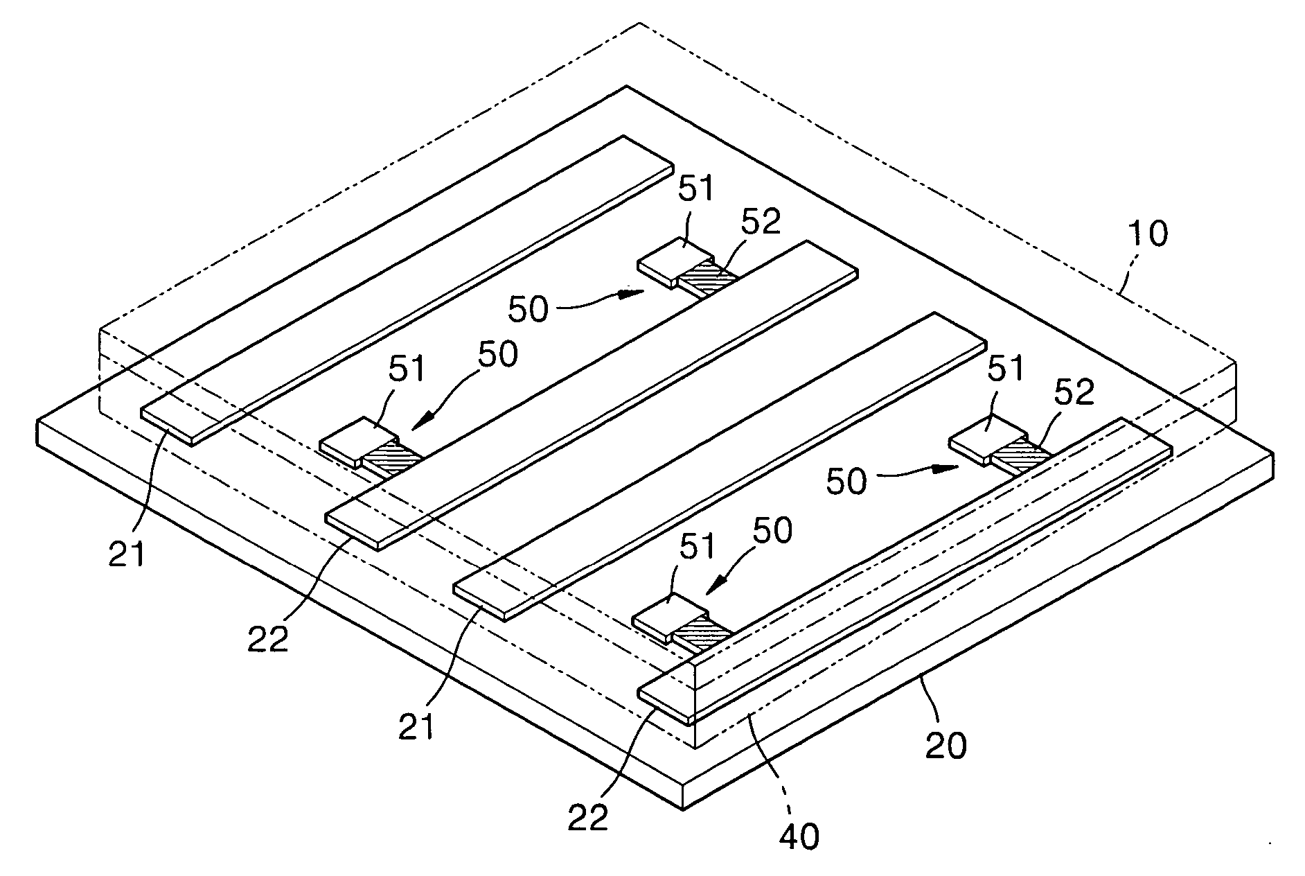
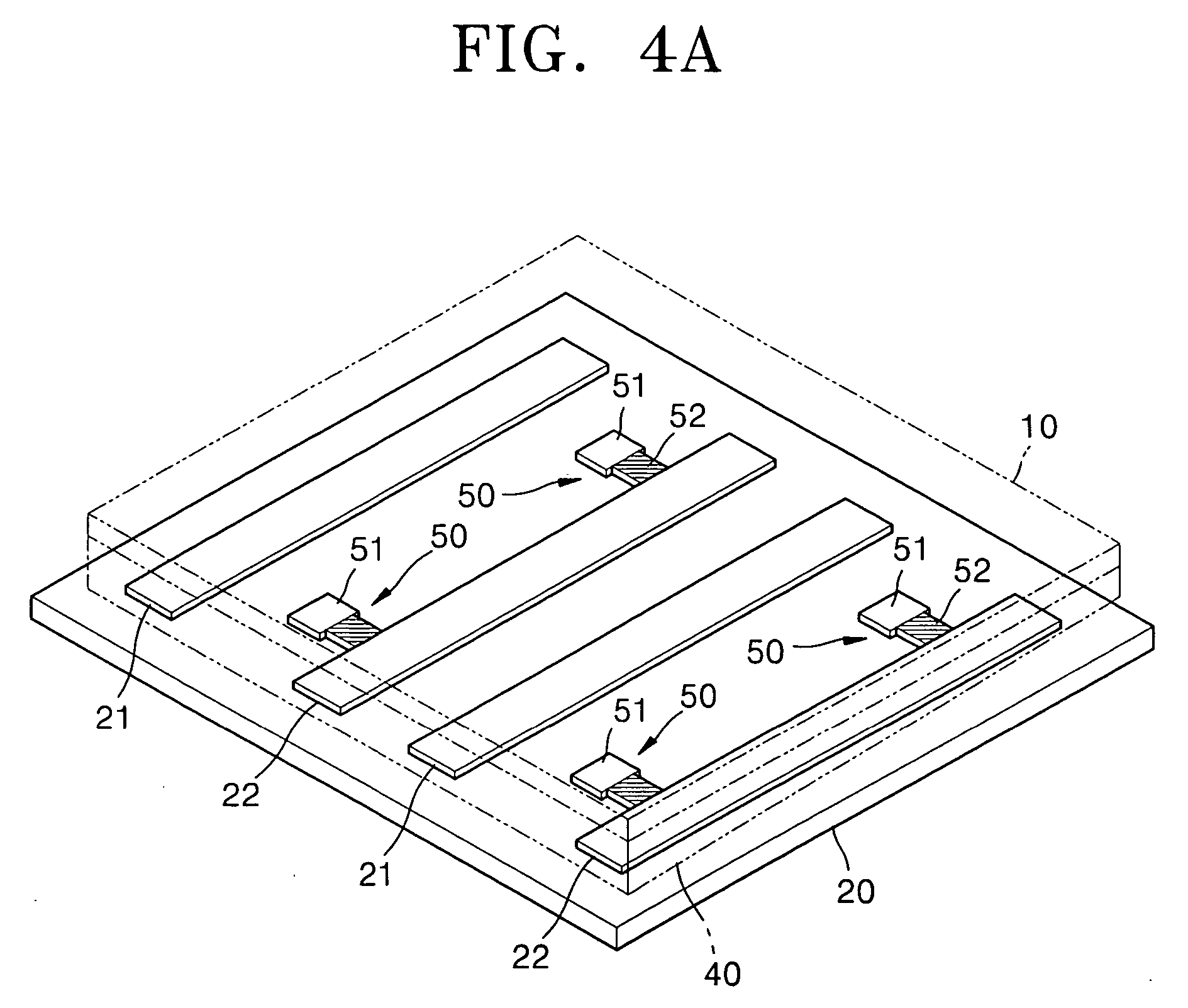
[0033]FIGS. 4A and 4B are views illustrating a plasma lamp according to a first embodiment of the present invention. Referring to FIGS. 4A and 4B, an upper plate 10 and a lower plate 20 are separated by a predetermined distance, and a discharge gas is filled in a space formed by the upper plate 10 and the lower plate 20. Two couples of first electrodes 21 and second electrodes 22 are arranged on the lower plate 20 in a row.

[0034] The upper plate 10 and the lower plate 20, which are separated by walls 40, form a discharge space 30 filled with a discharge gas. Fluorescent layers (not shown) are formed on the inner surfaces or any surfaces of the upper plate 10 and the lower plate 20.

[0035] Preliminary discharge units 50, which are a characteristic of the present invention, are formed on the second electrodes 22. Two pre...


PUM


Abstract

A plasma lamp includes a container filled with a discharge gas, a main discharge electrode unit located in the container and including a first electrode and a second electrode, which define a main discharge region of a first gap and generate a main discharge, and a preliminary discharge electrode unit having a high resistance unit and arranged on at least one of the first electrode and the second electrode, and located adjacent to the main discharge region to define a preliminary discharge region of a second gap, which is smaller than the first gap. The preliminary discharge electrode unit of the provided plasma lamp induces a preliminary discharge for a short time at a low voltage. A main discharge occurs conveniently due to charged particles generated by the preliminary discharge.

Description

BACKGROUND OF THE INVENTION [0001] This application claims the priority of Korean Patent Application No. 2003-53624, filed on Aug. 2, 2003, in the Korean Intellectual Property Office, which is incorporated herein in its entirety by reference. [0002] 1. Field of the Invention [0003] The present invention relates to a plasma lamp, and more particularly, to a plasma lamp having a low discharge voltage and a high light emitting efficiency. [0004] 2. Description of the Related Art [0005] Lamps developed as back-lights of liquid crystal displays (LCDs) are divided into a surface discharge type and a facing surfaces discharge type. Such a lamp is disclosed in US Patent application publication No. 2003 / 0098643 A1. [0006] Such a plasma lamp includes one or more unit discharge regions having two electrodes, which are arranged in a row. The electrodes are arranged while having a predetermined discharge gap in order to discharge uniformly. Here, discharges between the electrodes occur by AC or ...

Claims


Application Information

Patent Timeline
IPC IPC(8): H01J1/304H01J61/62H01J61/30H01J61/54H01K1/62
CPCB82Y10/00H01J1/304H01J2201/30469H01J61/542H01J61/305H01J61/62
Inventor KIM, GI-YOUNGCHUNG, DEUK-SEOKKIM, WON-SEOKKIM, YOUNG-MOCHUNG, KYUNG-MINSON, SEUNG-HYUNPARK, HYOUNG-BIN
Owner SAMSUNG ELECTRONICS CO LTD
Why Eureka
Try Eureka