Synthetic aperture ladar system and method using real-time holography

a technology of real-time holography and synthetic aperture ladar, which is applied in the field of target tracking and imaging systems, can solve the problems of increasing the required sensitivity several orders of magnitude, complex and expensive solar system for many current and future applications, and difficult to implement at optical wavelengths

Active Publication Date: 2005-03-17
RAYTHEON CO
View PDF4 Cites 82 Cited by
  • Summary
  • Abstract
  • Description
  • Claims
  • Application Information

AI Technical Summary

Benefits of technology

In an alternative embodiment, the back-scan mirror is eliminated, the medium is replaced with a video camera, and the read laser and imaging optical system is replaced with a holographic processing algorithm in a computer. One-dimensional and two-dimensio

Problems solved by technology

However, SAL systems tend to be too complex and costly for many current and future applications.
Phase errors resulting from nonlinear flight trajectories are compensated using SAR auto-focu

Method used


Image

  • Synthetic aperture ladar system and method using real-time holography
  • Synthetic aperture ladar system and method using real-time holography
  • Synthetic aperture ladar system and method using real-time holography

Examples


Embodiment Construction

Illustrative embodiments and exemplary applications will now be described with reference to the accompanying drawings to disclose the advantageous teachings of the present invention.

While the present invention is described herein with reference to illustrative embodiments for particular applications, it should be understood that the invention is not limited thereto. Those having ordinary skill in the art and access to the teachings provided herein will recognize additional modifications, applications, and embodiments within the scope thereof and additional fields in which the present invention would be of significant utility.

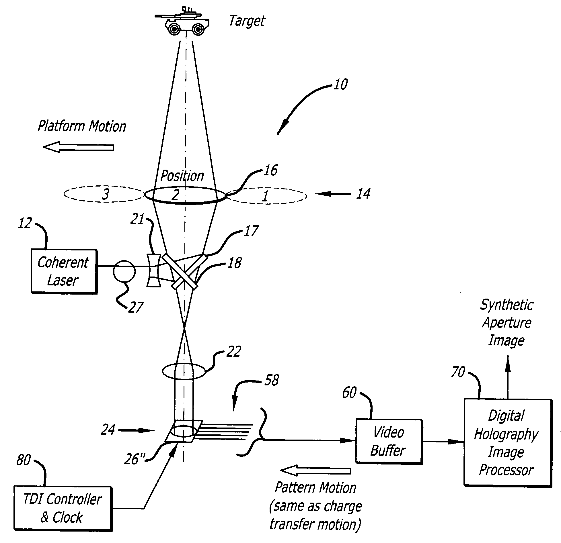
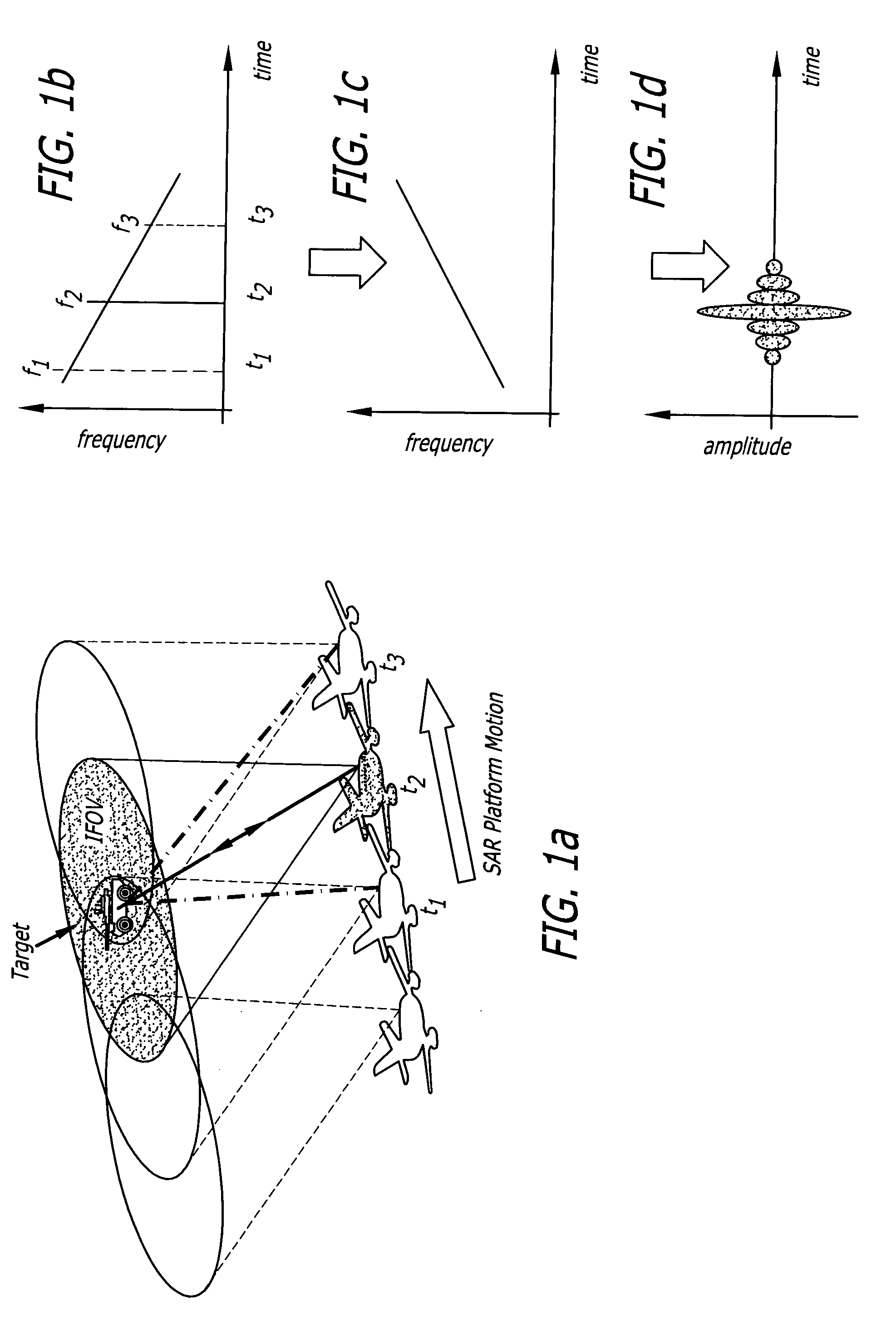
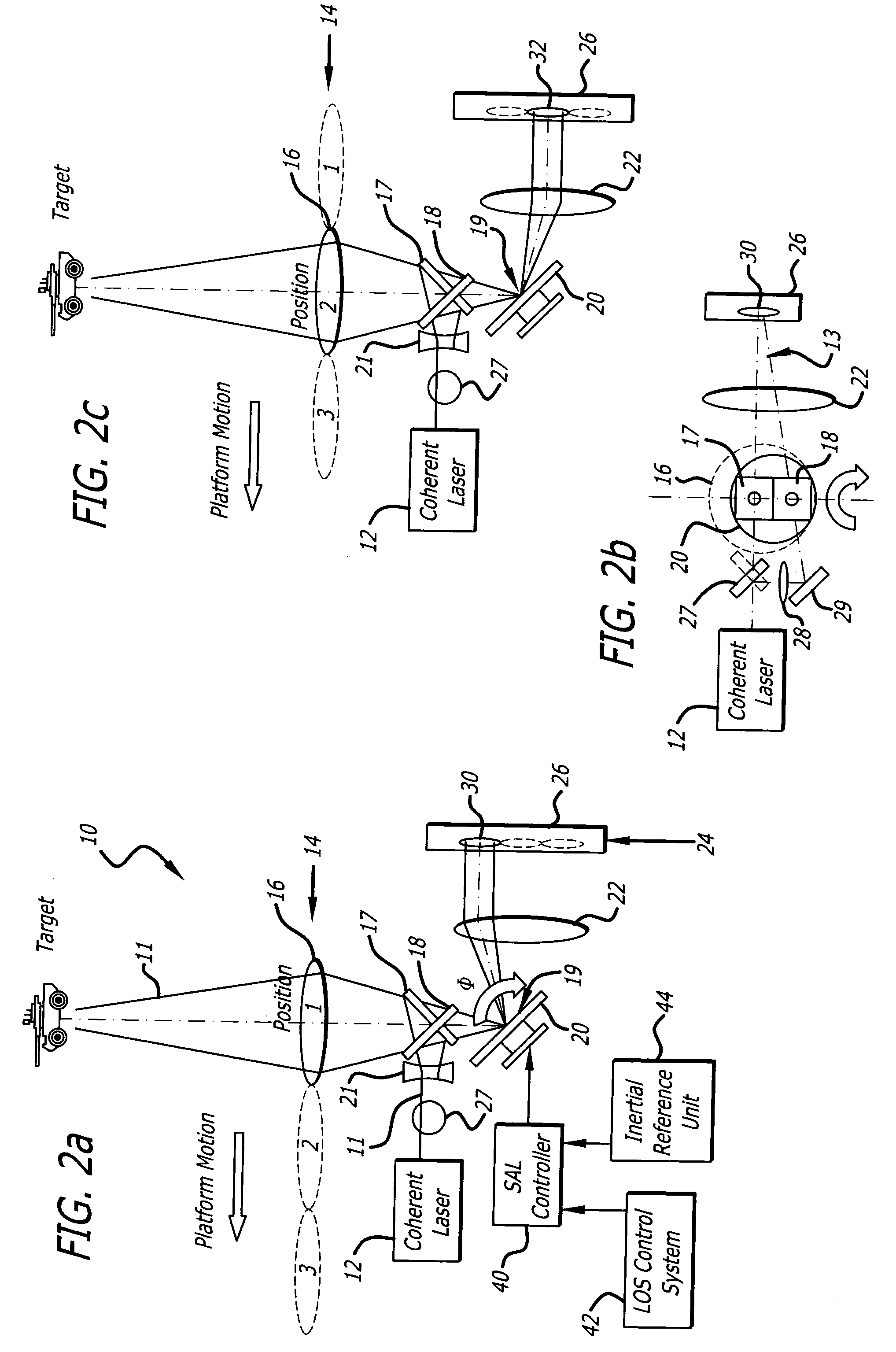
The objective of a synthetic aperture ladar (SAL) is to synthetically increase the effective aperture of the laser radar in order to increase the azimuth resolution of the image. The theory of operation of a traditional synthetic aperture radar or ladar based on coherent processing of the Doppler-shifted return signal is shown schematically in FIGS. 1a-c.

F...


PUM


Abstract

This invention uses a real-time holographic medium to record the amplitude and phase information collected from a moving platform at the aperture plane of a side-looking optical sensor over the collection time. A back-scan mirror is used to compensate platform motion during the synthetic aperture integration time. Phase errors caused by a nonlinear platform motion are compensated by controlling the phase offset between the illumination beam and the reference beam used to write the hologram based on inertial measurements of the flight path and the sensor line-of-sight pointing angles. In the illustrative embodiment, a synthetic aperture ladar (SAL) imaging system is mounted on a mobile platform. The system is adapted to receive a beam of electromagnetic energy; record the intensity and phase pattern carried by the beam; and store the pattern to compensate for motion of the platform relative to an external reference. In the illustrative embodiment, the image is stored as a holographic image. The system includes a back-scan mirror, which compensates the stored holographic pattern for motion of the platform. The medium and back-scan mirror may be replaced with a digital camera and one-dimensional and two-dimensional arrays may be used. In a specific embodiment, a two-dimensional array is used with a time delay and integration (TDI) scheme, which compensates for motion of the platform in the storage of the optical signals. In an alternative embodiment, a back-scanning mirror is used to compensate for motion of the platform. Consequently, the interference pattern between a relayed image of the aperture plane and a reference beam is continuously stored. In this embodiment, the instantaneous location of the received beam on the recording medium is controlled to compensate for motion of the platform.

Description

BACKGROUND OF THE INVENTION 1. Field of the Invention The present invention relates to systems and methods for target tracking and imaging. More specifically, the present invention relates to synthetic aperture ladar systems. 2. Description of the Related Art The resolution of a typical conventional radar system is dependent on the antenna size. Accordingly, unless the antenna diameter is quite large, the resolution is low. Synthetic aperture radar (SAR) provides a larger effective antenna size by virtue of the movement of the aperture relative to the target and integration of the returns from the target. However, current and future applications will require further improvements in resolution, particularly angular resolution, to achieve longer range and improved imagery. This need is addressed somewhat by synthetic aperture ladar (SAL). SAL systems are similar to radar systems with the exception that a laser pulse is transmitted as opposed to a radio wave. However, SAL systems ...

Claims


Application Information

Patent Timeline
IPC IPC(8): G01S17/90G01S7/481
CPCG01S7/481G01S17/895G01S7/4817G01S17/90
Inventor BYREN, ROBERT W.
Owner RAYTHEON CO
Why Eureka
Try Eureka