Region-based auto gain control and auto exposure control method and apparatus

an auto gain control and auto-adaptive technology, applied in the field of automatic adjustment of exposure and gain, can solve the problems of adversely affecting the captured image, automatic exposure and gain control algorithms, and carrying the risk of oscillation, so as to minimize oscillations and improve response time

Active Publication Date: 2005-03-17
MICRON TECH INC
View PDF4 Cites 59 Cited by
  • Summary
  • Abstract
  • Description
  • Claims
  • Application Information

AI Technical Summary

Problems solved by technology

Automatic exposure and gain control algorithms, however, carry the risk of oscillations.
If the desired exposure and gain and the actual exposure and gain do not converge, then oscillations result, which adversely impact the captured image.

Method used


Image

  • Region-based auto gain control and auto exposure control method and apparatus
  • Region-based auto gain control and auto exposure control method and apparatus
  • Region-based auto gain control and auto exposure control method and apparatus

Examples


Embodiment Construction

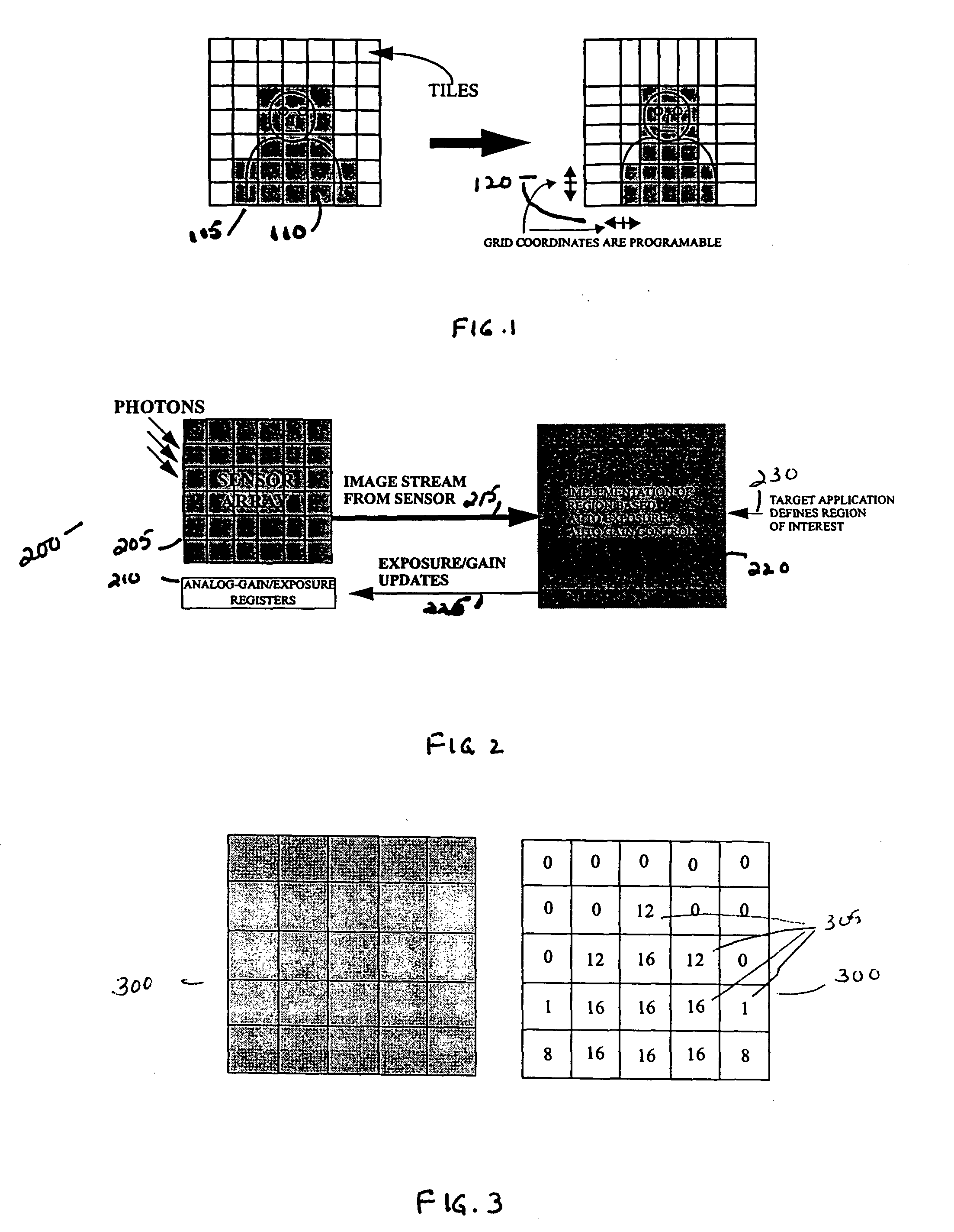
FIG. 1 shows a selection of tiles based on an object of interest 110 in a region of interest 115 (shaded tiles). Initially, the tiles 105 are defined by dividing the image field into tiles of equal size as illustrated in the tiles of the image field on the left of FIG. 1. Once a region of interest 115 has been identified based on the selection of an object of interest 110, the size of the tiles can be adjusted by adjusting the grid coordinates 120 of the tiles as illustrated in the tiles of the image field on the right of FIG. 1. The tiles of the region of interest 115 (shaded tiles) have been made smaller and the tiles outside of the region of interest 115 have been made larger.

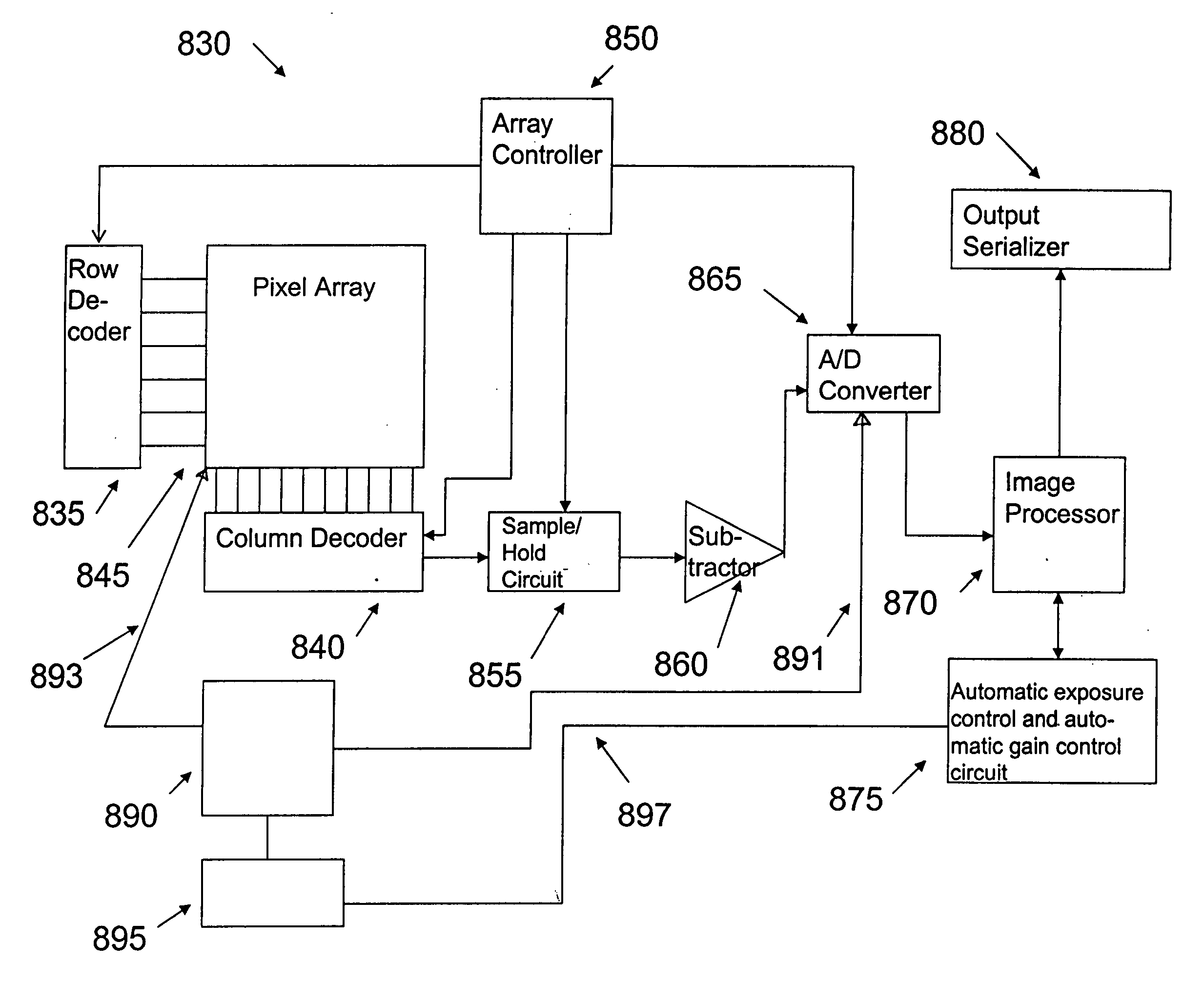
FIG. 2 is a block diagram of an auto-control feedback loop 200. The sensor array 205 has pixels, which accumulate charge based on an exposure to light. Analog exposure and gain registers 210 control the exposure and gain of the sensor array 205. An image stream 215 from the sensor array 205 is applied to the...


PUM


Abstract

An apparatus and method for performing automatic exposure and gain control while minimizing oscillations as well as providing a good response time, for example, a lag time or a settling time of about one frame. The automatic exposure and gain controls are performed not only on the image as a whole but on a weighted region of interest. If the contrast in the image exceeds the dynamic range of the sensor array, then the image in the region of interest will improve at the expense of the remainder of the image. A region of interest is a selected subset of tiles upon which automatic exposure and gain control will be based. The tiles are defined by a grid system having grid coordinates, which are programmable. Image sensors have to receive feedback with regular updates of exposure and gain settings based on ever changing light conditions.

Description

FIELD OF THE INVENTION The invention relates generally to automatic adjustment of exposure and gain, and in particular to a highly flexible region-based approach to automatic adjustment of exposure and gain for image sensors. BACKGROUND OF THE INVENTION CMOS imagers are low cost imaging devices. A fully compatible CMOS sensor technology enabling a higher level of integration of an image array with associated processing circuits would be beneficial to many digital applications such as, for example, in cameras, scanners, machine vision systems, vehicle navigation systems, video telephones, computer input devices, surveillance systems, auto focus systems, star trackers, motion detection systems, image stabilization systems and data compression systems for high-definition television. CMOS imagers have a low voltage operation and low power consumption; CMOS imagers are compatible with integrated on-chip electronics (control logic and timing, image processing, and signal conditioning s...

Claims


Application Information

Patent Timeline
Patent Type & Authority Applications(United States)
IPC IPC(8): H04N5/20H04N5/235H04N5/243
CPCH04N5/2351H04N5/243H04N5/2353H04N5/2352H04N23/72H04N23/71H04N23/73H04N23/76
Inventor HU, SHANE CHING-FENGSARWARI, ATIF
Owner MICRON TECH INC
Why Eureka
Try Eureka