Optical storage device, optical device and servo controlling method therefor

a technology of optical storage device and servo control method, which is applied in the direction of data recording, instruments, disposition/mounting of heads, etc., can solve the problems of inability to find a relative state between a disk and an objective lens, the objective lens may contact, and the stopper cannot be provided to avoid collision between the objective lens and the disk, so as to reduce the risk of collision of the objective lens, improve the effect of focusing, and positive make the focus point to be reached

Inactive Publication Date: 2005-03-17
FUJITSU LTD
View PDF4 Cites 5 Cited by
  • Summary
  • Abstract
  • Description
  • Claims
  • Application Information

AI Technical Summary

Benefits of technology

[0048] It is another object of the present invention to realize stable focus entry control even in the case where a focus error signal is used with which the focus error signal sensitivity and the level in the vicinity of a focus point vary depending on the light path length.
[0050] According to the present invention, by using the second focus error signal having the wide detection range, the objective lens is caused to approach the disk while maintaining the predetermined rate of change with respect to time. Hence, it is possible to positively make the focus point to be reached while maintaining arbitrary relationships of relative distance / relative speed between the objective lens and the disk. Accordingly, when switching to focus servo according to a first accurate focus error signal, it is possible to control an initial condition to fall within a fixed range. Thus, it is possible to realize stable focus entry. Hence, even in an apparatus having a short working distance, it is possible to significantly reduce the risk of collision of the objective lens with the disk at the time of focus entry.
[0051] In addition, according to the present invention, the rate of change with respect to time of a moving objecting lens is controlled. Thus, it is possible to maintain focus entry speed within a fixed range. Accordingly, even in the case where the characteristics of the second focus error signal vary depending on the light path length, it is possible to realize stable focus entry.

Problems solved by technology

In a case where focus entry fails in the oscillating operation, there is a possibility that the objective lens may contact a disk.
Considering that vertical run-out of a disk due to rotation is several dozen to several hundred μm, it is impossible to provide a stopper for avoiding collision between the objective lens and the disk.
However, in the conventional method where focus entry is performed by an oscillation operation of an objective lens, it is impossible to find a relative state between a disk and the objective lens until the S curve of the focus error signal is detected.
It is very difficult to perform focus servo control by a DSP whose sampling time for the focus error signal is 10 μs.
In this embodiment, however, it is necessary to mount the sensor to the actuator, which adversely affects reduction of the size and weight of the actuator.
Thus, in an apparatus where the distance between the objective lens and a disk is very narrow, there is a risk the lens and the disk may collide with each other.
Thus, there is a problem in that the distance from the focus and the signal sensitivity depend on the total light path length.
On this occasion, since the position of the objective lens is outside the linear range of the first focus error signal, it is impossible to stably switch to the first focus error signal.
Thus, at this time point, since it is outside the linear signal detection range of the first focus error signal, large overshooting occurs at the time of transition to servo control according to the first focus error signal.

Method used


Image

  • Optical storage device, optical device and servo controlling method therefor
  • Optical storage device, optical device and servo controlling method therefor
  • Optical storage device, optical device and servo controlling method therefor

Examples


Embodiment Construction

[0071] A description is given below of an embodiment for performing the present invention with reference to the drawings.

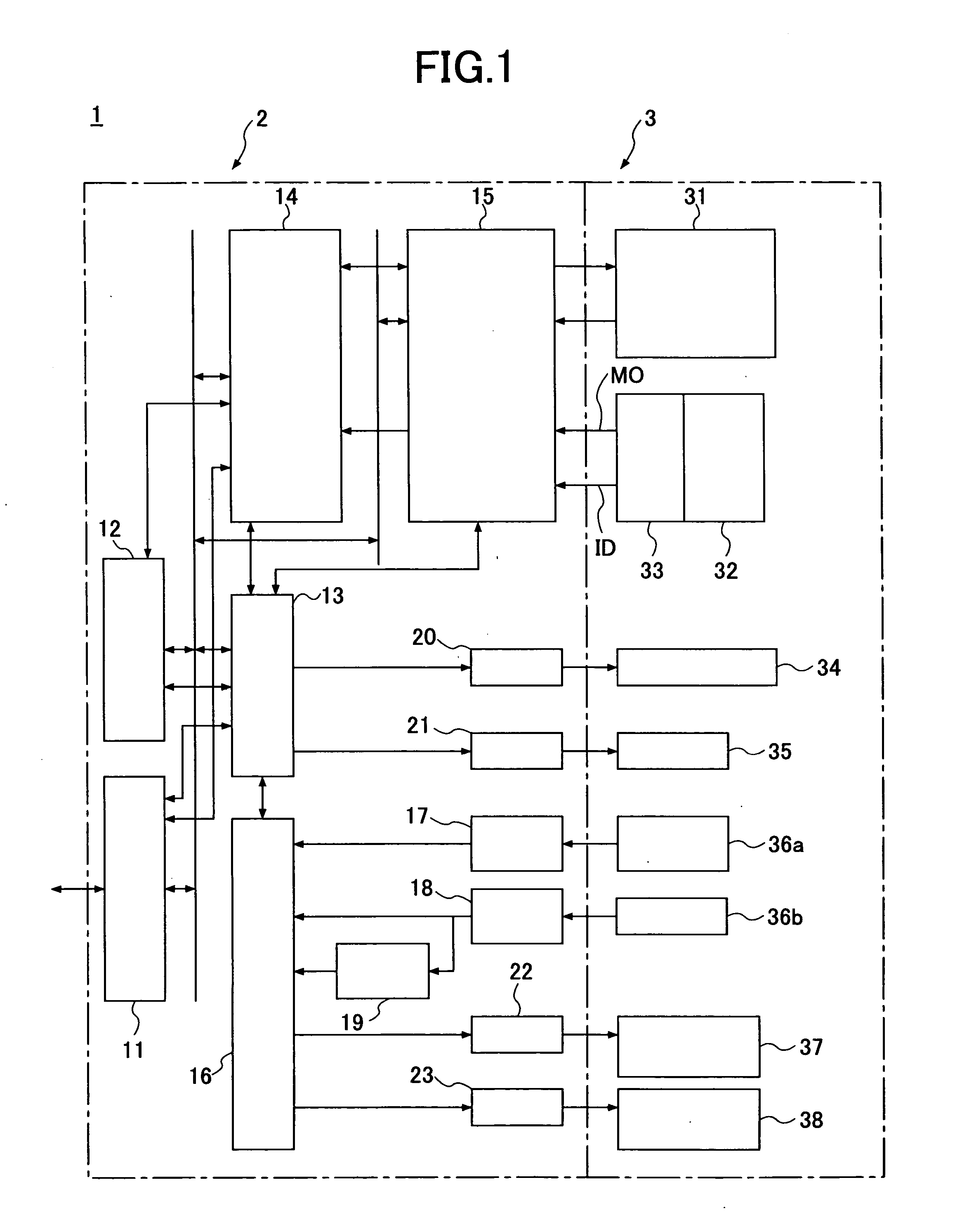
[0072]FIG. 10 is a block diagram of a focus entry control part of an optical disk device. Although a description is given of the case where the focus entry control part is hardware, the focus entry control part may be realized as software that is executed in the DSP 16 of FIG. 1. The focus entry control part shown in FIG. 10 is formed mainly by comparing parts 1001, 1002, 1003 and 1004, an approach control output generation part 1005, a target trajectory generation part 1006, a subtracting part 1007, a first phase compensation part 1008, a second phase compensation part 1009, and a focus actuator driving part 1010. In addition, a focus entry control start signal 1020, a second focus error signal 1021, and a threshold value 1022 are input to the comparing part 1001. An output signal 1027 of the comparing part 1001, the second focus error signal 1021, and a thresho...


PUM

PropertyMeasurementUnit
relative speedaaaaaaaaaa
focal depthaaaaaaaaaa
relative speedaaaaaaaaaa

Abstract

An object of the present invention is to realize stable focus entry control even in the case where a wideband focus error signal is used with which the focus error signal sensitivity and the level in the vicinity of a focus point vary depending on a light path length. In order to achieve the object, the present invention uses a second focus error signal having a wide range, causing an objective lens to approach a disk while maintaining a predetermined rate of change with respect to time, and, during approach, a transition to focus servo is performed by detecting the focus position according to the first focus error signal.

Description

CROSS-REFERENCE TO RELATED APPLICATION [0001] This application is a U.S. continuation application, filed under 35 USC 111(a) and claiming the benefit under 35 USC 120 and 365(c), of PCT application PCT / JP02 / 08273, filed Aug. 14, 2002. The foregoing application is hereby incorporated herein by reference.BACKGROUND OF THE INVENTION [0002] 1. Field of the Invention [0003] The present invention relates to optical storage devices and servo control methods thereof and, more particularly, to an optical storage device and a servo control method that oscillate a lens with respect to an object. [0004] 2. Description of the Related Art [0005] In optical storage devices such as a disk device, in order to perform accurate recording / reproducing, focus servo control is performed such that a laser beam is focused on a recording film surface of a disk. In the focus servo control, by feeding back a focus error signal, an objective lens is controlled such that the distance between the objective lens a...

Claims


Application Information

Patent Timeline
Patent Type & Authority Applications(United States)
IPC IPC(8): G11B7/085G11B7/09G11B7/13G11B7/131
CPCG11B7/08511G11B7/131G11B7/0916G11B7/0912
Inventor KAWABE, TAKAYUKI
Owner FUJITSU LTD
Why Eureka
Try Eureka