Thermo-optic plasmon-polariton devices

a technology of plasmon polariton and optical plasmon, which is applied in the direction of optics, instruments, optical light guides, etc., can solve the problems of insatisfactory known devices, time-consuming process, and less than optimal energy efficiency of devices

Inactive Publication Date: 2005-03-17
SPECTALIS
View PDF12 Cites 59 Cited by
  • Summary
  • Abstract
  • Description
  • Claims
  • Application Information

AI Technical Summary

Benefits of technology

According to one aspect of the present invention, there is provided a waveguide structure formed by a thin strip of material having a relatively high free charge carrier density surrounded by material having a relatively low free charge carrier density, the strip having finite width and thickness with dimensions such that optical radiation having a wavelength in a predetermined range couples to the strip and propagates along the length of the strip as a plasmon-polariton wave, and heater means for causing heating of the strip to vary propagation of said optical radiation.

Problems solved by technology

However, only a fraction of the heated region overlaps well with the waveguide to influence the propagation of light, resulting in less than optimal energy efficiency for the device.
Generally, despite such efforts to improve response times for a given power, these known devices are not entirely satisfactory, primarily because the heat source is located a distance away from the optical waveguide core.
Consequently, heat must diffuse from the source into the waveguide core in order to affect the light confined therein, which is a time consuming process.
Furthermore, heat diffuses away from the source in many directions: while some of the heat is directed towards the waveguide, a significant amount is lost and unused.
It is known to add trenches each side of the waveguide to limit lateral heat diffusion, but this is at the expense of increased fabrication complexity and slower switching times. Also, some of the prior art devices are sensitive to the ambient temperature and require temperature control.
Finally, device size and manufacturing costs are other problems with some of the prior art devices.
Thus, a disadvantage of these known devices generally is that they suffer from one or more of the following limitations: high power consumption, low energy efficiency, complex temperature control requirements, large device size, complex fabrication requirements, inaccurate thermal sensing, and poor optical performance.

Method used


Image

  • Thermo-optic plasmon-polariton devices
  • Thermo-optic plasmon-polariton devices
  • Thermo-optic plasmon-polariton devices

Examples


Embodiment Construction

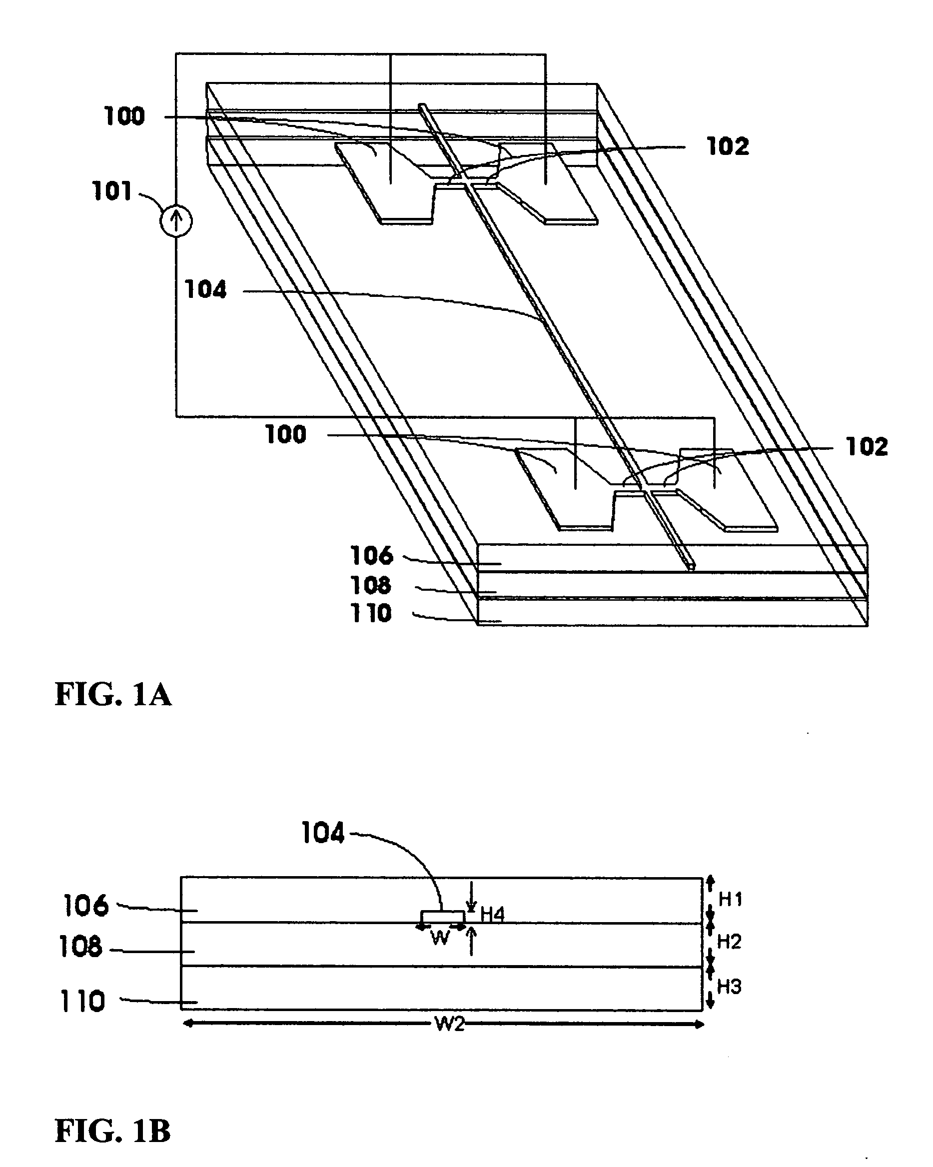
In the following description, a straight waveguide VOA will be referred as a SWGVOA while a VOA based on a MZ configuration will be referred as a MZVOA. Also, the terms “plasmon-polariton wave” and “optical mode” used herein refer to the main long-ranging plasmon-polariton wave supported by the waveguide and denoted ssn0 in the afore-mentioned U.S. Pat. No. 6,442,321. The terms “waveguide heater” and “waveguide monitor” will be used herein when referring to the strip (which with the surrounding material forms the optical waveguide) being used as a heating element and a temperature monitor, respectively.

FIGS. 1A and 1B and show the basic structure of a SWGVOA. The SWGVOA comprises a core 104 of predetermined length. The desired properties of the core of the waveguide 104 include a negative real permittivity, a small imaginary permittivity and high thermal diffusivity, in order for the core 104 to be able to produce heating and still maintain low optical loss, the core material 104 ...


PUM


Abstract

A waveguide structure comprises a thin strip of material having a relatively high free charge carrier density surrounded by material having a relatively low free charge carrier density. The width and thickness of the strip are dimensioned such that optical radiation having a wavelength in a predetermined range couples to the strip and propagates along its length as a plasmon-polariton wave. The device includes a waveguide heater for passing a current through the strip to heat it and the surrounding material, so as to vary propagation of the optical radiation, or means for monitoring propagation of the optical radiation to determine a change in temperature of the strip. Some embodiments provide both heating of the strip and monitoring of its temperature.

Description

BACKGROUND OF THE INVENTION 1. Technical Field The invention relates to thermo-optic waveguide structures in which an optical characteristic of the structure changes in dependence upon a change in temperature, and to devices employing such a waveguide structure. The invention also relates to such waveguide structures having means for monitoring variations in temperature of part of the waveguide structure. 2. Background Art This specification refers to several published articles, For convenience, the articles are cited in full in a numbered list at the end of the description and cited by number in the specification itself. The contents of these articles are incorporated herein by reference and the reader is directed to them for reference. In the context of this patent specification, the term “optical radiation” embraces electromagnetic waves having wavelengths in the infrared, visible and ultraviolet ranges. The terms “finite” and “infinite” as used herein are used by persons s...

Claims


Application Information

Patent Timeline
Patent Type & Authority Applications(United States)
IPC IPC(8): G02B6/00
CPCG02B6/12007G02B6/1221B82Y20/00G02F1/0147G02F2203/10G02B6/1226
Inventor BERINI, PIERRE SIMON JOSEPHGAGNON, GUY PHILIPPEJETTE, STEPHANIE MARIE-JULIE
Owner SPECTALIS
Why Eureka
Try Eureka