Identification information issuing system

a technology of identification information and issuing system, which is applied in the direction of digitally marking record carriers, instruments, payment protocols, etc., can solve the problem of almost impossible to forge secondary identification information without regularity in relation to primary identification information before the expiration time is reached

Inactive Publication Date: 2005-03-17
CODECOM
View PDF5 Cites 99 Cited by
  • Summary
  • Abstract
  • Description
  • Claims
  • Application Information

AI Technical Summary

Benefits of technology

[0008] An object of the present invention is to provide an identification information issue system or the like that, even when identification

Problems solved by technology

Forging the secondary identification information having no regularity in relation to the pr

Method used


Image

  • Identification information issuing system
  • Identification information issuing system
  • Identification information issuing system

Examples


first embodiment

[0215] First Embodiment

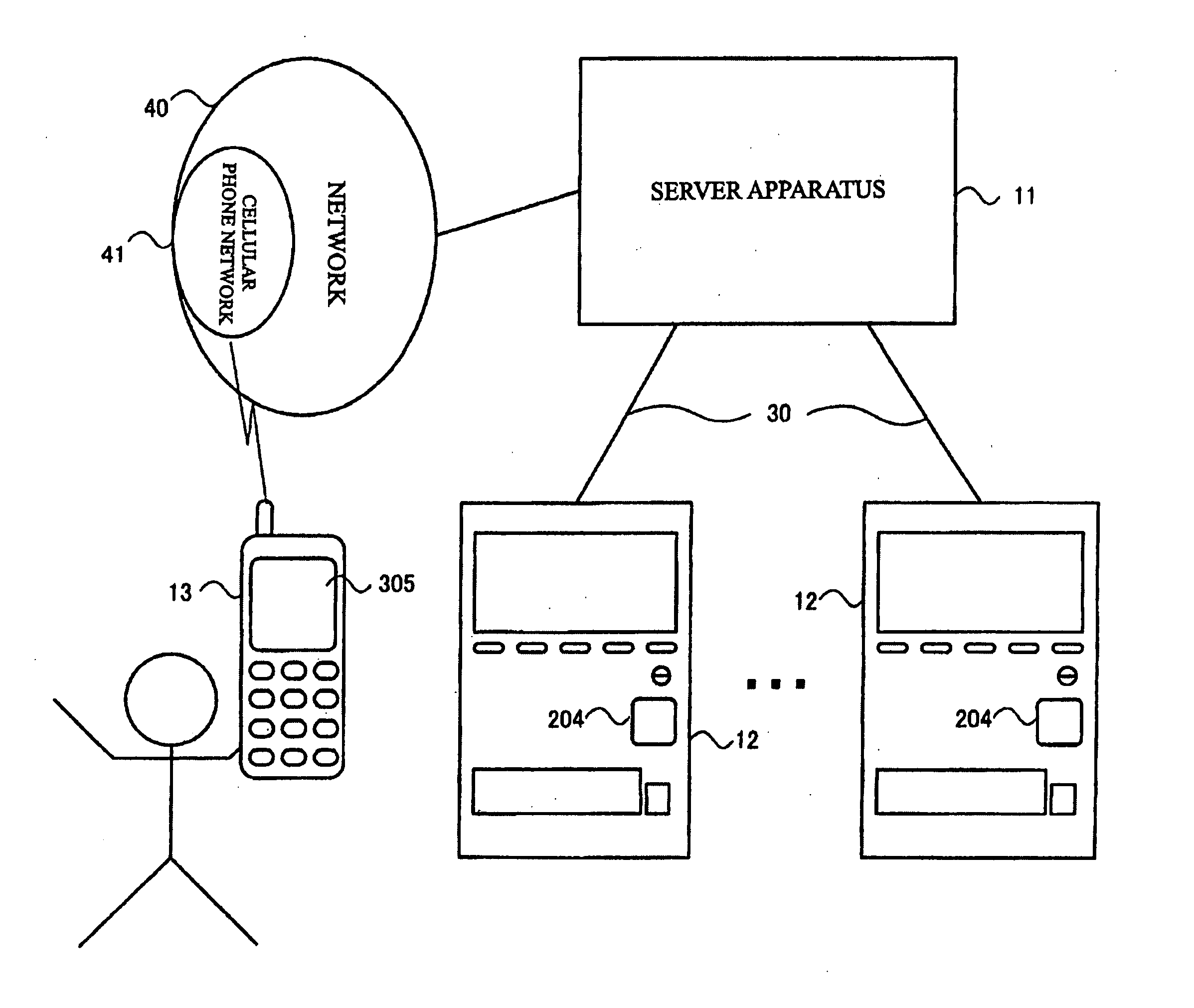
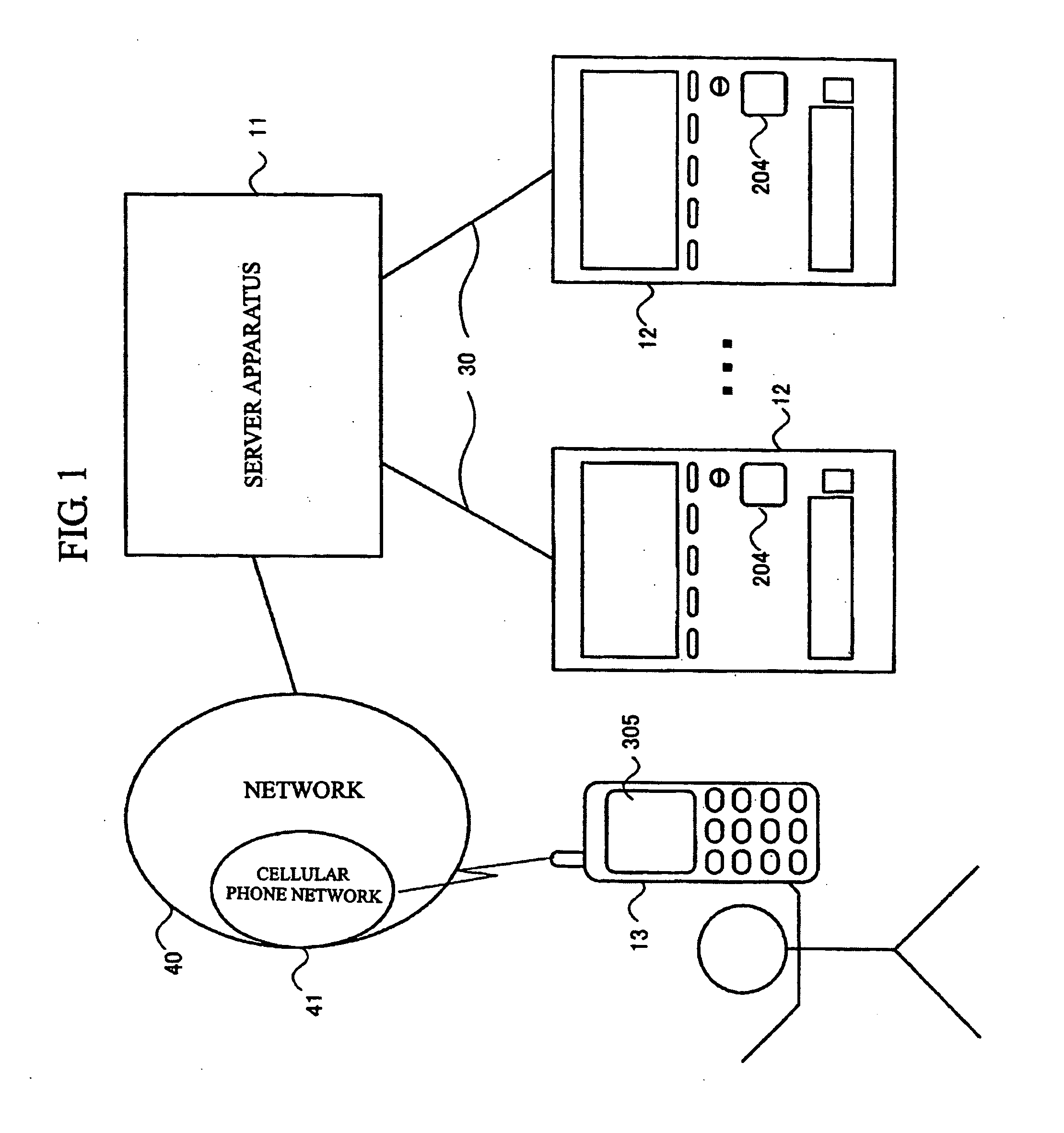
[0216]FIG. 1 is a block diagram showing the configuration of a vending machine system to which the present embodiment is applied. As shown in FIG. 1, the vending machine system includes a server apparatus 11; vending machines 12 each having a bar code reader 204; and a cellular phone 13 having a display unit 305. The server apparatus 11 and the vending machines 12 are connected via corresponding leased lines 30. The server apparatus 11 and the cellular phone 13 are connected via a network 40 that includes at least a cellular phone network 41.

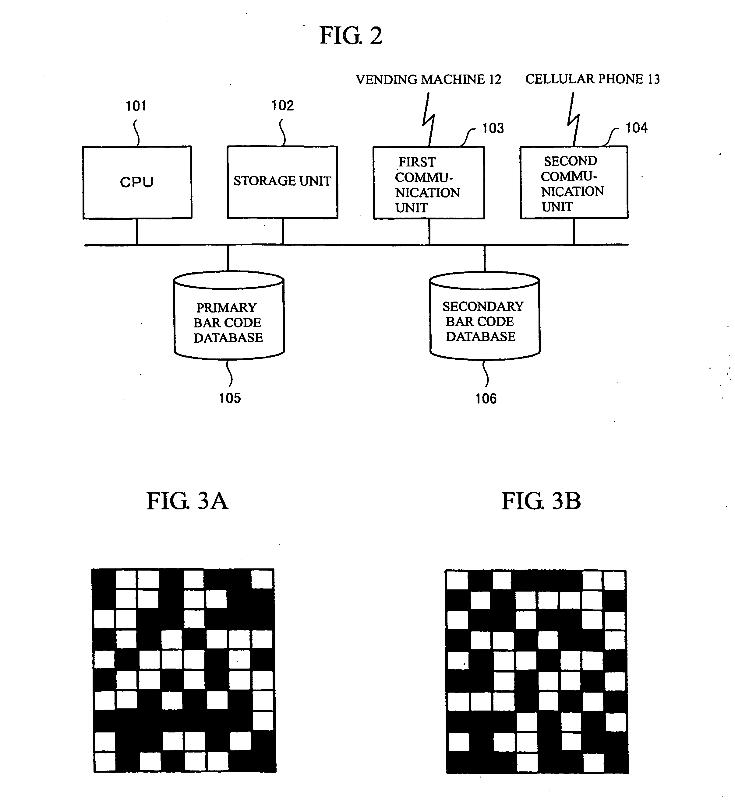
[0217]FIG. 2 is a block diagram showing the configuration of the server apparatus 11. As shown in FIG. 2, the server apparatus 11 includes a CPU (Central Processing Unit) 101; a storage unit 102; a first communication unit 103; and a second communication unit 104. The server apparatus 11 further includes a primary bar code database 105 and a secondary bar code database 106. In actuality, the primary bar code database 105 ...

second embodiment

[0258] Second Embodiment

[0259] In the above-described first embodiment, the primary bar codes and the secondary bar codes of users are stored in the primary bar code database 105 and the secondary bar code database 106, respectively, of the server apparatus 11 as images. In other words, the primary bar code and the secondary bar code of a user are managed not only in the cellular phone 13 of the user but also in the server apparatus 11. The present embodiment is a vending machine system capable of providing the same service as that provided by the first embodiment without managing the primary and secondary bar codes in the server apparatus 11.

[0260]FIG. 10 is a block diagram showing the configuration of the server apparatus 11 in the present embodiment. The server apparatus 11 in the present embodiment includes a user database 107 in place of the primary bar code database 105 and the secondary bar code database 106. The details of the user database 107 will be described later, but ...


PUM


Abstract

When image data of a bar code displayed on a cellular phone and read by a vending machine or the like are sent to a server apparatus, the apparatus converts the code to a numerical value. The apparatus divides the code value by divisor A to obtain remainder a, and divides the code value by divisor B to obtain remainder b. The least common multiple for the numeric value A and the numeric value B is greater than the difference between the maximum and minimum values that the bar code value assumes. The apparatus refers pointers registered in a storage position corresponding to remainder a in the first table and pointers registered in a storage position corresponding to remainder b in the second table. The apparatus authenticates the user when the same user information in a user database can be accessed from both the first table and the second table.

Description

CROSS-REFERENCE TO RELATED APPLICATIONS [0001] This application is entitled to the benefit of and incorporates by reference essential subject matter disclosed in International Application No. PCT / JP02 / 02989 filed on Mar. 27, 2002; PCT / JP01 / 10083 filed on Nov. 19, 2001; and Japanese Patent Application No. 2001-249397 filed on Aug. 20, 2001.FIELD OF THE INVENTION [0002] The present invention relates to technology for preventing a fraudulent act that could otherwise be carried out on the basis of fraudulently obtained identification information. BACKGROUND OF THE INVENTION [0003] Commodities available on the market include age-restricted commodities, such as liquors and cigarettes. Specifically, an age limit is imposed on those who can purchase age-restricted commodities. The ability to freely purchase such age-restricted commodities at any time from vending machines is convenient for purchasers, but may incur drinking or smoking by minors. In order to cope with the problem, studies ha...

Claims


Application Information

Patent Timeline
IPC IPC(8): G06K1/12G06Q10/00G06Q20/00G06Q20/40G06Q20/42G06Q30/06G06Q50/00G07G1/00H04L29/06H04L29/08
CPCG06K1/12G06Q20/18G06Q20/20G06Q20/32G06Q20/3274H04L69/329G06Q30/06G07G1/0045H04L29/06H04L67/04H04L67/12G06Q20/4014G06F17/00G06F15/00H04L9/32G06F21/00H04L9/40
Inventor HONDA, TOSHINOBUUGAWA, TARO
Owner CODECOM
Why Eureka
Try Eureka