Double pull body brace

Active Publication Date: 2005-03-17
ASPEN MEDICAL PROD LLC
View PDF3 Cites 96 Cited by
  • Summary
  • Abstract
  • Description
  • Claims
  • Application Information

AI Technical Summary

Benefits of technology

[0005] It is, thus, a purpose and advantage of this invention to provide a one-piece body brace which wraps around the torso and is secured by overlapping fasteners to minimize twisting in the plane of the fasteners.
[0006] It is a further purpose and advantage of this invention to provide a one-piece body panel wraparound body brace formed of a one-piece body panel which engages around the torso of the patient. Upper and lower sinuous cords are engaged on separate top and bottom one-piece molded cord guides which are laterally spaced from each other and secured onto the one-piece body panel so that, when the cords are pulled in opposite directions, the panel is effectively shortened. Separate tightening of the upper and lower cords achieves separate tightening of the upper and lower portions of the body panel. Pulling in opposite directions provides balance to the pulling forces for beneficial ergonomic effect.
[0007] It is a further purpose and advantage of this invention to provide a body brace which is formed of a one-piece wraparound body panel which has spaced cor

Problems solved by technology

For many users, back braces are difficult to appropriately position and fasten.
Without being consistently worn and properly adjusted, the effectiveness is substantially reduced.
One problem with back braces is their need to conform to the torso as it changes.
Chung U.S. Pat. No. 6,322,529 teaches the use of force multiplicatio

Method used


Image

  • Double pull body brace
  • Double pull body brace
  • Double pull body brace

Examples


Embodiment Construction

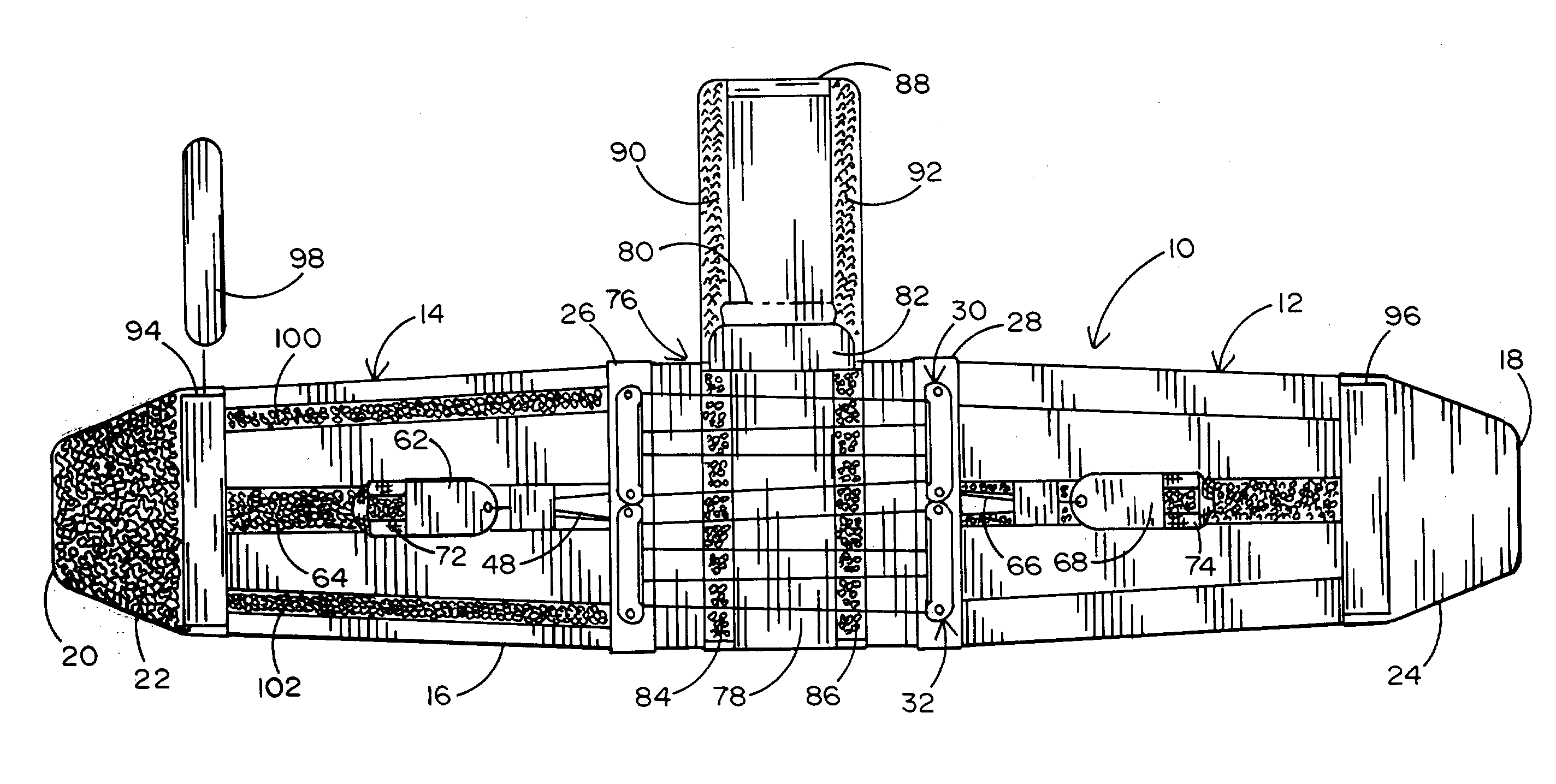
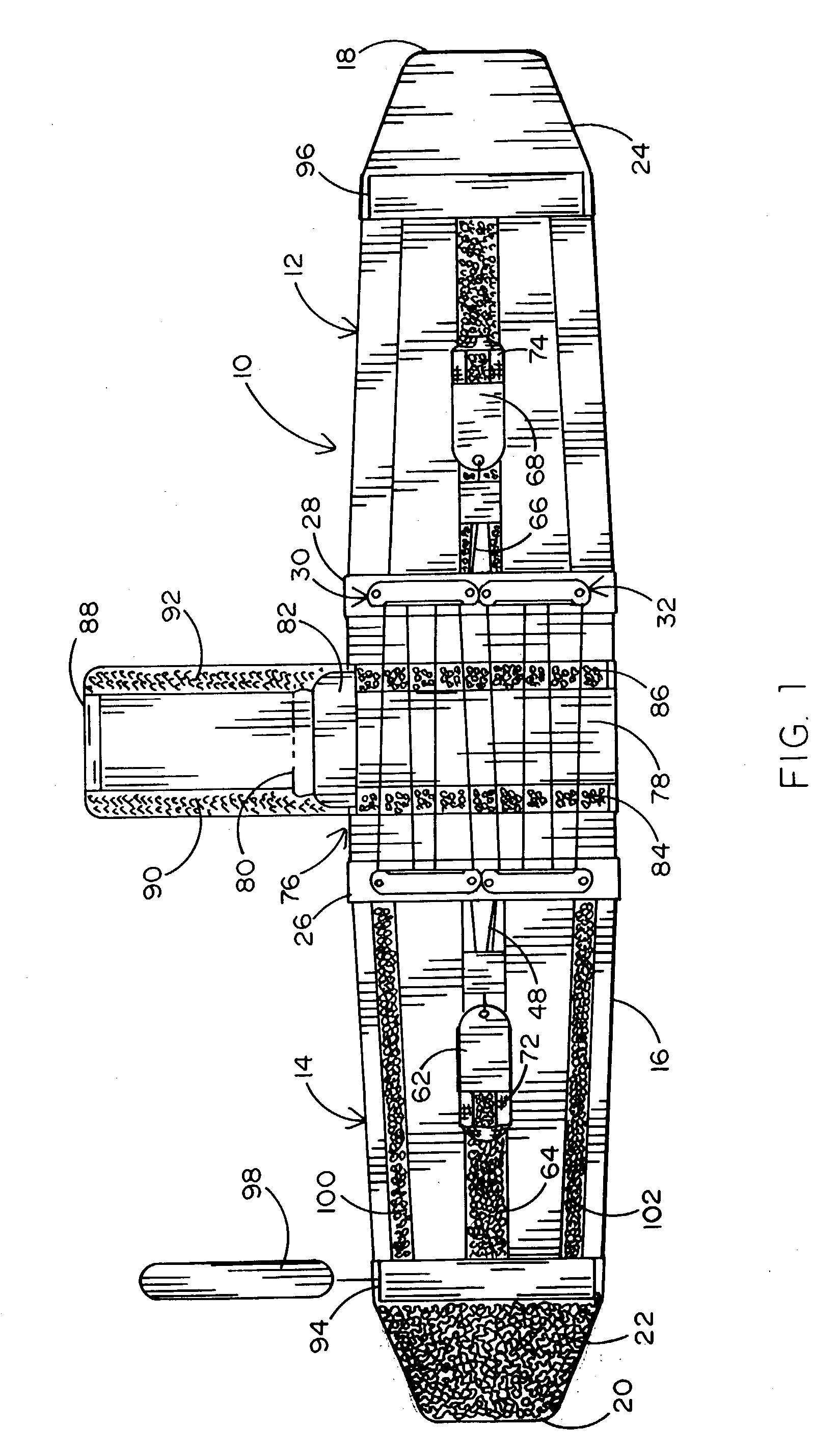
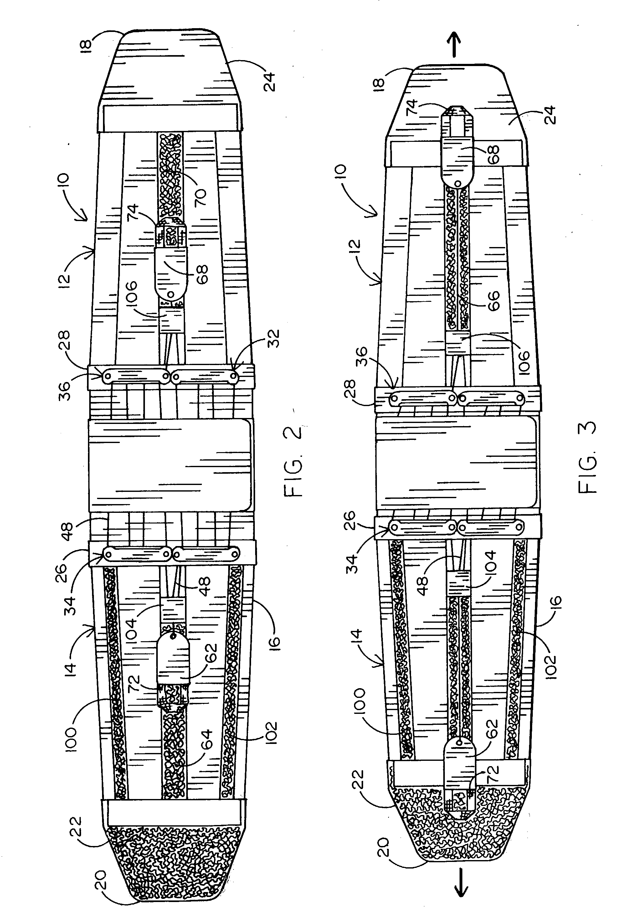
[0017] The preferred embodiment of the one-piece back brace of this invention is generally indicated at 10 in FIGS. 1, 2, 3 and 6. The back brace 10 has a one-piece panel which extends from top edge 14 to bottom edge 16 and from right end 18 to left end 20. This orientation is seen by the wearer as he dons the back brace. He holds the back brace behind him with the right end to his right and the top edge upward and engages it around his torso. The panel 12 is flexible and easily wraps around his torso with the ends overlapping. A hook-and-loop fastener system in the overlap area engages the left and right ends to hold them as desired. Loop assembly 22 is attached to the outside of the panel 12 adjacent its end to form the loop panel. A hook panel is secured to the underside of attachment panel 24 adjacent the right end. The material of the one-piece panel 12 may be synthetic polymer sheet material of good flexibility or may be a polymer netting material. The panel 12 is preferably m...


PUM


Abstract

The double pull body brace comprises a one-piece panel which engages around the torso and overlaps at the front. At the overlap, it is attached to itself by means of a hook-and-loop fastener so that a wide range of adjustment is possible. In the back, spaced cord guides are mounted on said panel. Each cord guide carries a plurality of cord guide lobes. An upper cord is engaged around the upper cord guide lobes, and a lower cord is engaged around the lower cord guide lobes. These cords are separately attached to pull tabs. When donned, the user pulls on the pull tabs to separately adjust upper and lower closure tension of the body brace. When in correct adjustment, the pull tabs are attached in place by hook-and-loop fasteners.

Description

FIELD OF THE INVENTION [0001] This invention is directed to a lumbar support which is formed by a one-piece wraparound body panel with front closure and a back tightening system. The tightening system has right and left pull tabs which separately tighten the upper and lower potions of the body panel. BACKGROUND OF THE INVENTION [0002] Orthotic devices are provided for partial or substantial immobilization of the torso to stabilize the back. These orthotic devices are back braces which can be fitted snugly around the torso. Such back braces are effective in achieving spinal stability if worn properly. For many users, back braces are difficult to appropriately position and fasten. Without being consistently worn and properly adjusted, the effectiveness is substantially reduced. One problem with back braces is their need to conform to the torso as it changes. The torso may change from moment to moment as the patient moves between the standing and the sitting positions. In addition, the...

Claims


Application Information

Patent Timeline
IPC IPC(8): A61F5/02
CPCA61F5/028A61F5/02A61F2250/001
Inventor GARTH, GEOFFREY C.ROMO, ALBERT V.
Owner ASPEN MEDICAL PROD LLC
Why Eureka
Try Eureka