Method and apparatus for stereotactic implantation

a stereotactic and implantation technology, applied in the field of stereotactic implantation instruments, can solve the problems of reducing the likelihood of additional surgery, and the probability of a successful procedure, so as to facilitate the precise placement of instruments, enhance the surgeon's ability to prepare the disc space, and enhance the surgeon's ability to position the shell

Inactive Publication Date: 2005-03-17
COMPANION SPINE LLC
View PDF92 Cites 33 Cited by
  • Summary
  • Abstract
  • Description
  • Claims
  • Application Information

AI Technical Summary

Benefits of technology

The methods and apparatus of the invention satisfy this need by providing a technique for precisely locating a preferred location for positioning a device, such as a joint prosthesis. There are numerous ways to describe and characterize the techniques outlined herein, either in terms of locating and positioning with regard to various reference points, lines or planes. In accordance with one such characterization, generally, the desired preferred location is found by precisely locating a line containing a predetermined point within the surgical site using a series of levels and plumb lines and internal anatomical features of the surgical site, using this location to precisely position and temporarily affix a site preparation machining jig or scaffold relative to the patient's anatomy so that site preparation instruments can be introduced into the site at precise locations governed by the scaffold geometry and patient anatomy. The surgical site may be, for example, a target disc space having a damaged spinal disc, or a site created by removal of bone growth associated with an earlier fusion of two vertebrae. This precise positioning of the scaffold also provides a way for the surgeon to use patient anatomical features to reliably and precisely prepare the surgical site. This increased precision in site preparation increases the probability of a successful procedure, and decreases the likelihood that additional surgery may be needed.
Because the position of the patient with respect to gravity is used in conjunction with the patient's anatomical features to precisely locate a predetermined point within the surgical site, there is no need to place the patient in a particular orientation relative to the surgeon or operating table, or to vary that position during surgery. For instance, for anterior cervical discectomy and arthroplasty, the patient is merely immobilized with the patient's spine in its preoperative lordosis, in a position suitable for a normal anterior approach. An image of the patient's spine can be taken to ensure that the spinous processes of the relevant vertebrae are as close as possible to midway between the facet joints. However, once the patient is immobilized in an appropriate position, there is no need to move the patient or the operating table to accommodate the procedure.
In either case, this line forms an axis for positioning a machining fixture or scaffold, upon which can be mounted the instruments for preparing a cavity in the endplates adjacent the target disc space. This cavity can then be used to receive the implant. Once the implantation cavity is precisely prepared using instruments located as described herein, the shape of the cavity and the corresponding shape and features of the prosthesis can serve to appropriately position the prosthesis, and maintain such positioning.
In another embodiment, this procedure relates to providing instruments that are adapted to enhance the surgeon's ability to prepare the disc space to receive an endoprosthesis having two articulating outer shells. More specifically, the instruments enhance the surgeon's ability to position the shells such that they are substantially parallel to one another within the disc space when the patient's spine assumes a normal position while standing without flexion or extension. In some instances, to achieve parallel shell positions when the patient is standing in a neutral position, it is preferable to prepare the vertebral body endplates at an angle relative to the machining instrument. Such an angle is useful to compensate for any deviation from the normal lordosis or kyphosis of the spine (i.e. curvature while standing in a neutral position) caused by the horizontal positioning of the patient on the operating table or non parallel positioning of the vertebral bodies resulting from distraction. It is thus desirable to provide a procedure that allows for machining the vertebral body endplates at a controlled specified angle, and that provides instruments adapted to accommodate such angled machining processes. In another embodiment, this invention relates to a method for machining the vertebral body endplates at an angle to prepare the inter-vertebral disc space for receiving the endoprosthesis and to instruments facilitating this method.
Additionally, this invention also relates to a surgical procedure and associated instruments, wherein an intervertebral endoprosthesis is implanted within more than one disc space of the spine. In this embodiment, a first intervertebral endoprosthesis is placed according to the methods described herein, and a second endoprosthesis or a plurality of endoprostheses are subsequently placed at levels or disc spaces immediately adjacent to the level of the first endoprosthesis. A modified machining fixture is used in the second or subsequent procedures. As with the standard machining fixture, the modified machining fixture facilitates precise placement of the instruments. The multiple-level technique and instrumentation can be used to implant multiple endoprostheses during a single surgery, or they may be used to implant an endoprosthesis at an adjacent level during a second surgery.
A modified machining fixture is beneficial for this procedure because it allows reuse of a fixation device used to secure the machining fixture during the first procedure. This eliminates the need to drill additional holes to accommodate the fixation device in the common vertebral body between the two adjacent target disc spaces. If multiple holes are drilled there is a chance that the second hole would intersect with and unnecessarily enlarge the first hole already formed, which would likely cause the machining fixture fixation device, and thus the machining fixture, to become unstable during the procedure.

Problems solved by technology

This increased precision in site preparation increases the probability of a successful procedure, and decreases the likelihood that additional surgery may be needed.

Method used


Image

  • Method and apparatus for stereotactic implantation
  • Method and apparatus for stereotactic implantation
  • Method and apparatus for stereotactic implantation

Examples


Embodiment Construction

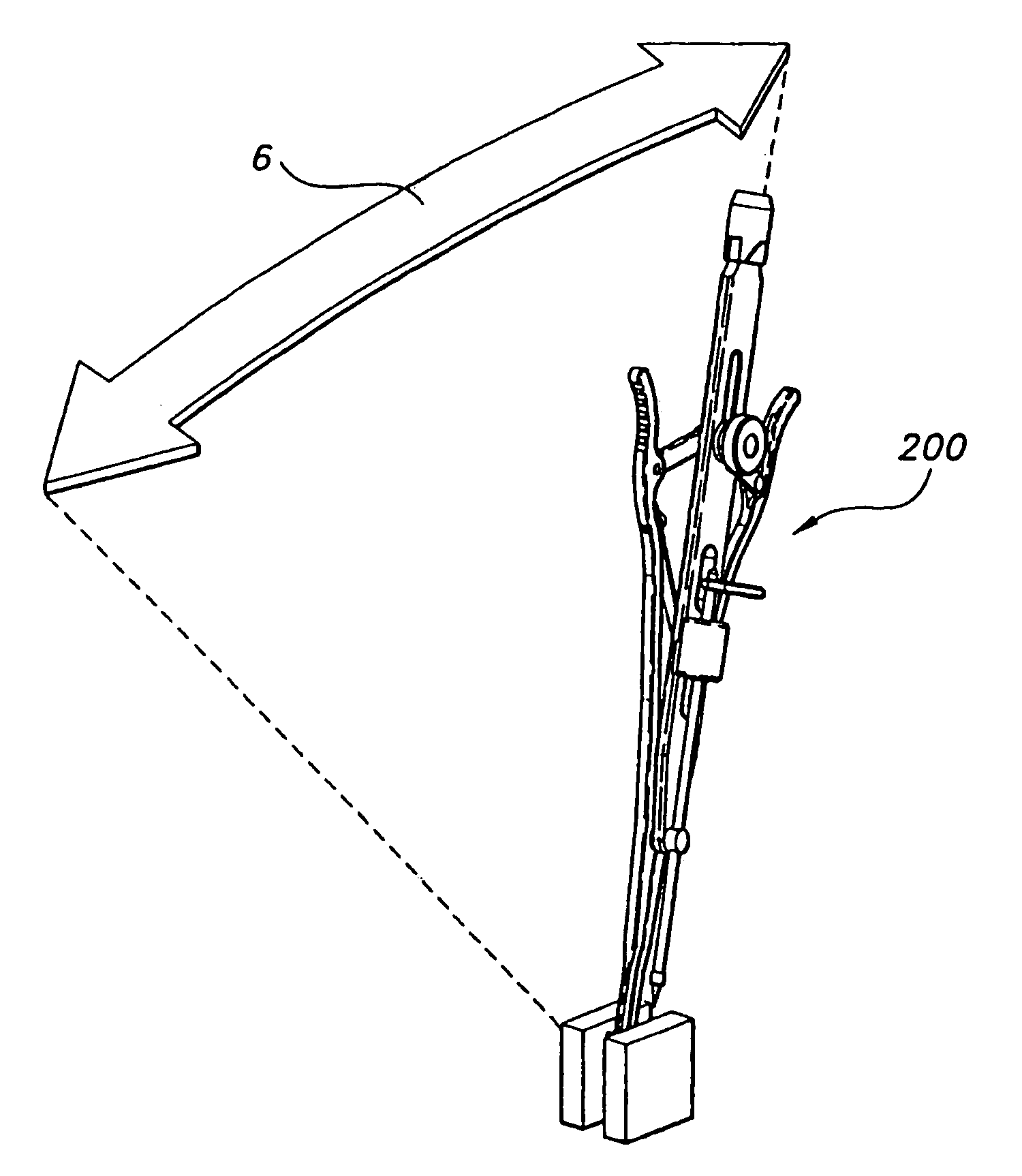
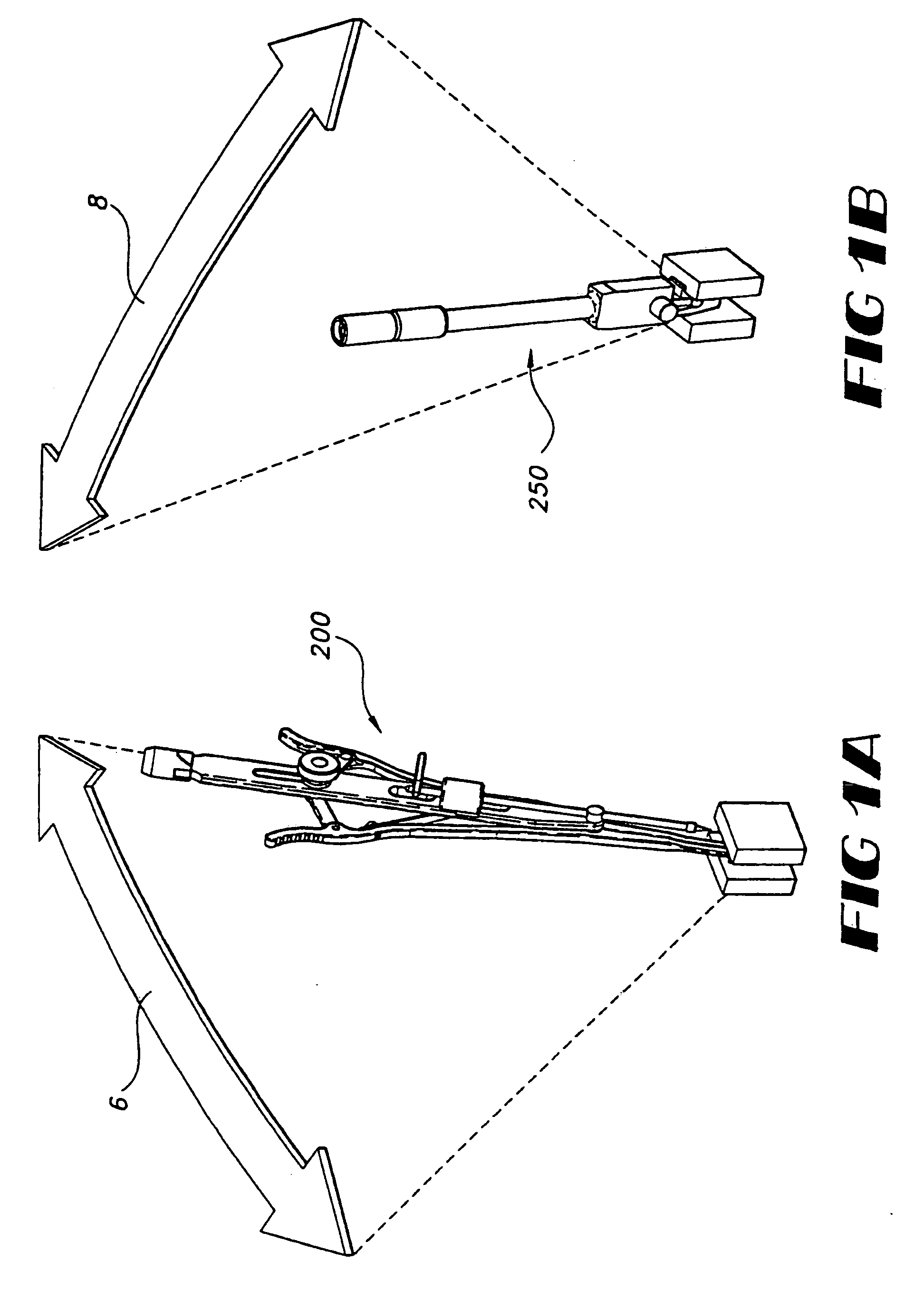
It will be understood from the description above that the techniques of this invention are applicable to a wide variety of surgical procedures where stereotactic precision is required. The described procedure and instruments generally provide a system and method for locating and targeting a precise location. The description that follows focuses on one embodiment of the invention, namely the implantation of an intervertebral endoprosthesis, and in particular, to the implantation of such an endoprosthesis in the intervertebral space between cervical vertebrae using an anterior approach. Those of skill in the art will recognize that the procedure described below can be varied or modified to be applicable to other spinal implants such as fusion implants or to other approaches, or to lumbar or thoracic vertebral implants, to implants in other parts of the body, such as hips, knees, elbows, or other joints, and to other procedures that do not involve implantation.

1. Brief Overview of P...


PUM


Abstract

The invention relates to a technique for precisely locating a line containing a predetermined point within the surgical site using a series of levels and plumb lines and internal anatomical features of the surgical site, using this location to precisely position and temporarily affix a site preparation scaffold relative to the patient's anatomy so that site preparation instruments can be introduced into the site at precise locations governed by the scaffold geometry and patient anatomy. This precise positioning of the scaffold also provides a way for the surgeon to use patient anatomical features to reliably and precisely prepare the surgical site. Scaffolds having angling features further increase the precise preparation of the surgical site. This increased precision in site preparation increases the probability of a successful procedure, and decreases the likelihood that additional surgery may be needed.

Description

BACKGROUND OF THE INVENTION 1. Field of the Invention The invention relates to methods and associated instrumentation for stereotactically locating the site of a prosthetic implant in a body, and in particular to methods and associated instrumentation for stereotactically locating and preparing the site for an intervertebral endoprosthesis, and to precisely implanting the endoprosthesis. 2. Description of Related Art The proper location of any endoprosthetic implant is a key element of the success of the implantation procedure in improving patient quality of life. In spinal implants, for example, properly locating the endoprosthesis ensures among other benefits that the patient will enjoy the full range of motion offered by the implant. The use of intervertebral implants (arthroplasty) has, in recent years, attained increasing acceptance as a preferable alternative to spinal fusion (arthrodesis) as a method for treating patients where discectomy is indicated. This is in part du...

Claims


Application Information

Patent Timeline
Patent Type & Authority Applications(United States)
IPC IPC(8): A61B19/00A61B17/02A61B17/16A61B17/17A61B17/56A61B17/88A61B19/02A61F2/00A61F2/30A61F2/44A61F2/46
CPCA61B17/02A61F2310/00239A61B17/1671A61B17/1757A61B17/8866A61B19/0256A61B19/20A61B19/26A61B2017/0256A61B2017/1602A61B2019/304A61F2/30742A61F2/30744A61F2/442A61F2/4425A61F2/4611A61F2002/30204A61F2002/30235A61F2002/30474A61F2002/30499A61F2002/30528A61F2002/30563A61F2002/30578A61F2002/30616A61F2002/30673A61F2002/30682A61F2002/30769A61F2002/30772A61F2002/443A61F2220/0025A61F2230/0065A61F2230/0069A61F2310/00017A61F2310/00023A61F2310/00029A61F2310/00203A61B17/0293A61B90/10A61B90/50A61B50/20A61B2090/034A61F2002/302A61F2002/30495
Inventor BRYAN, VINCENTKUNZLER, ALEXCONTA, ROBERTALLARD, RANDYBROMAN, RICHARD J.FINAZZO, ANTHONYGIL, CARLOS E.ROULEAU, JEFFREY P.TOKISH, LEONARD JR.YAGER, DAVID
Owner COMPANION SPINE LLC
Why Eureka
Try Eureka