Multi-axial prosthetic foot

a multi-axial, prosthetic foot technology, applied in the field of prosthetics, can solve the problems of limited capacity, difficult and expensive, limited energy storage and return capabilities, etc., and achieve the effect of increasing the energy storage and return function

Inactive Publication Date: 2005-03-17
OTTO BOCK HEALTHCARE IP GMBH & CO KG
View PDF16 Cites 46 Cited by
  • Summary
  • Abstract
  • Description
  • Claims
  • Application Information

AI Technical Summary

Benefits of technology

[0018] Further, a heel member and heel buffer may be added to the lower member to increase the energy storage and return function.

Problems solved by technology

While the Rosenkranz prosthesis looked like the part being replaced, it provided only limited energy storage and return capabilities.
While the Voisin prosthetic foot provided some multi-axial capability, this capability was limited.
However, the Wilson et al. prosthetic device used three ball joints making it difficult and expensive to make.
While the Harris et al. prosthetic foot allowed for multi-axial movement of the prosthetic foot relative to the pylon, it was complex and required many assembly steps to manufacture.
While the Phillips '569 prosthetic foot allows for motion either fore and aft or laterally, it really does not allow for wide multi-axial motion of the foot relative to the pylon.
However, wide multi-axial function was not achieved.
This foot, however does not provide energy storage and return.
The Itsuro prosthetic does not, however, allow movement around more than one axis.
While many different multi-axial motion artificial feet have been made, they have been complex and expensive to build, or they lack true multi-axial capability with energy storage and return.

Method used


Image

  • Multi-axial prosthetic foot
  • Multi-axial prosthetic foot
  • Multi-axial prosthetic foot

Examples


Embodiment Construction

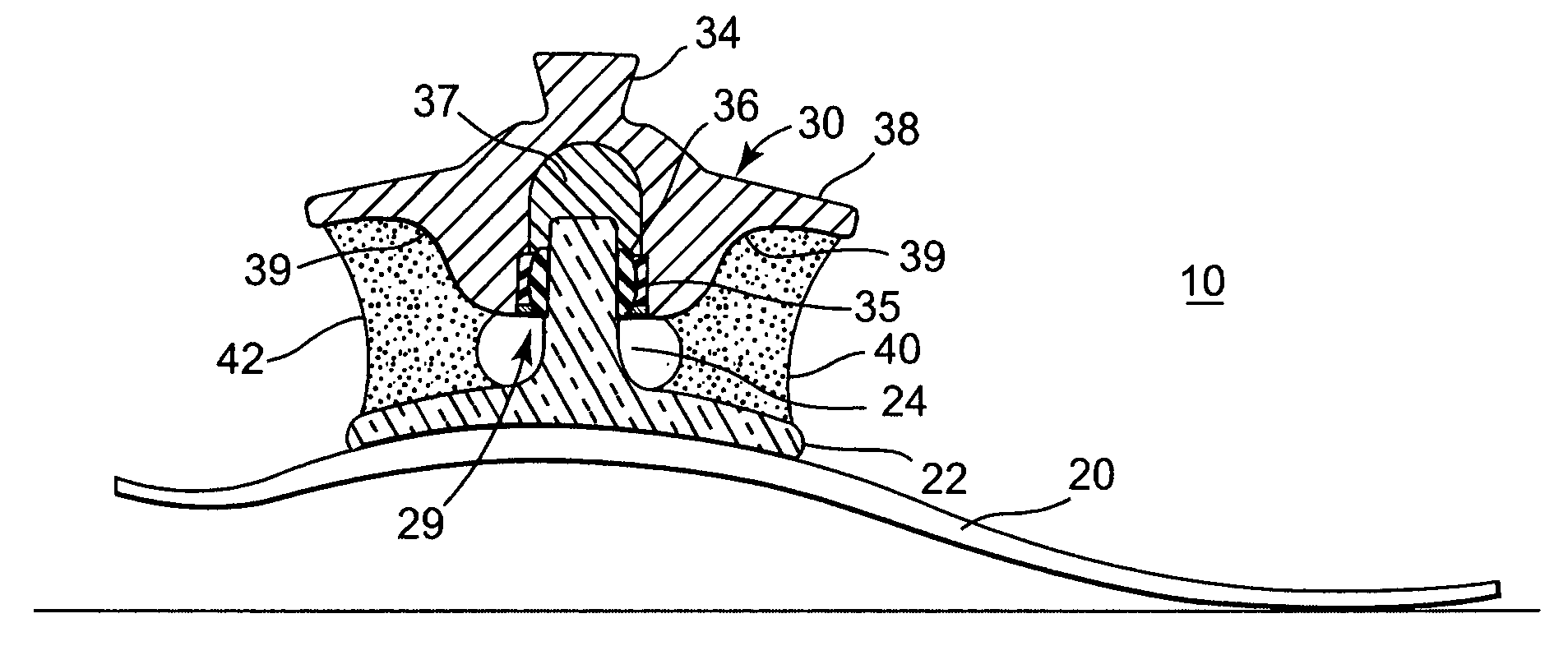
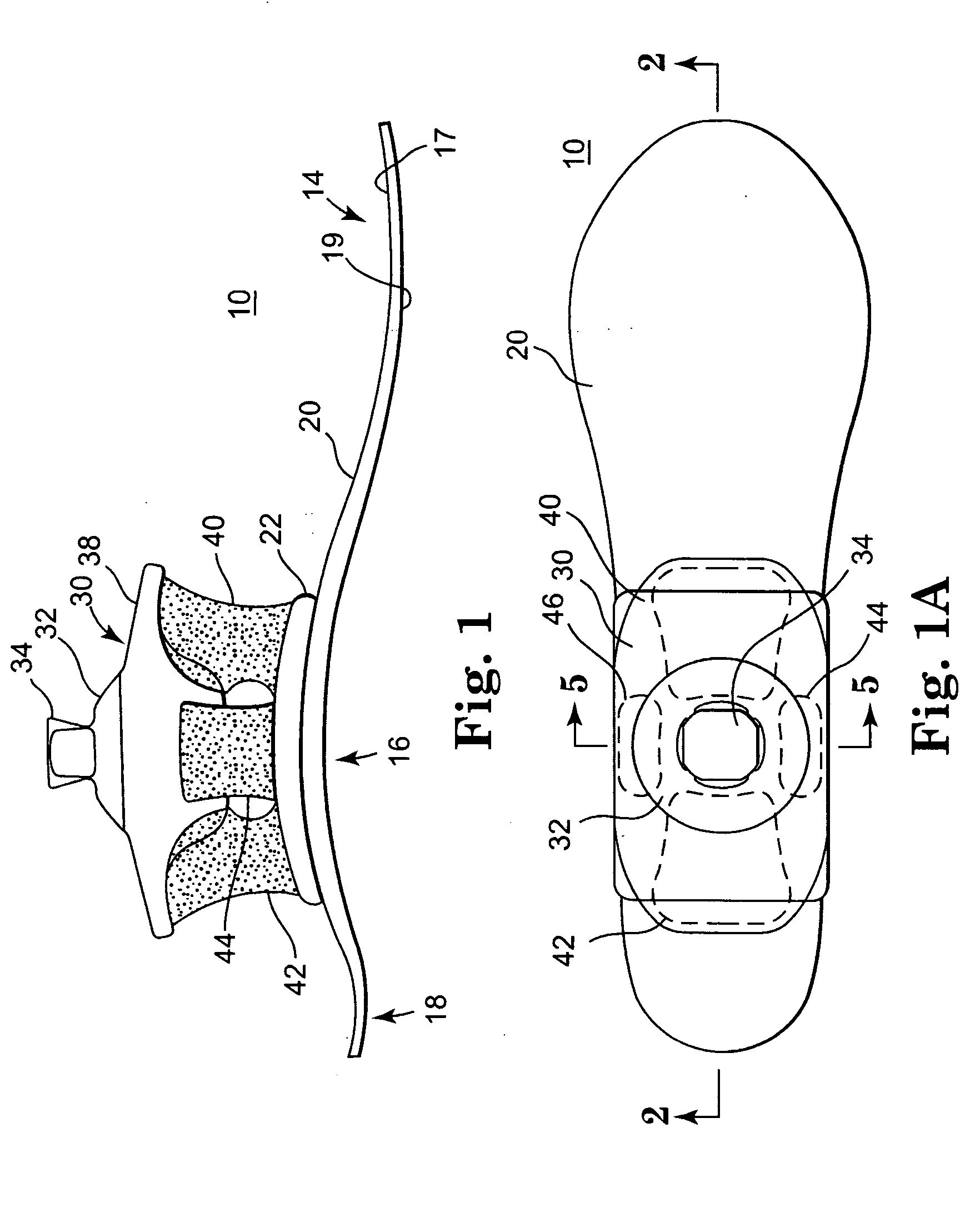
[0037] Referring now to FIGS. 1 and 1A, there shown is a side view of the prosthetic foot 10 of the present invention. Lower member 20 provides a base for upper member 30 on which the wearer (not shown) of the prosthetic foot 10 will stand. The lower member 20 includes anterior, medial, and posterior portions 14, 16, and 18. In one embodiment, the lower member 20 can be roughly the size of a human foot and shaped similarly to a human foot. The width of the lower foot member 20 can be variable along its length. In the illustrated embodiment, the width of its anterior portion 14 can be greater than the widths of its medial and posterior portions 16 and 18. In another embodiment, the widths of its anterior and posterior portions 14 and 18 can be greater than the width of its medial portion 16 (not shown). In yet another embodiment, the width of the lower foot member 20 can be constant along its length (not shown).

[0038] The lower foot member 20 includes a top surface 17 and a bottom s...


PUM


Abstract

A simple, wide ranging multi-axial foot with energy return and/or storage. An upper member and a spaced apart lower member are joined through a post connected to the lower member and a ball joint connected to the upper member. One buffer is located anterior to the ball joint-post, one buffer is located posterior to the ball joint-post. A heel member and heel buffer provide additional energy storage and return.

Description

TECHNICAL FIELD [0001] This invention relates to the field of prosthetics and more particularly to joints in prosthetic feet. BACKGROUND OF THE INVENTION [0002] Prosthetic devices have evolved through the years from simple blocks of a material placed on a stump of a limb to sophisticated energy storage and return devices which can be formed to look like the missing part. Further, a goal of these improvements is to provide better feedback and therefore more comfort and usefulness to the wearer. [0003] A number of prosthetic feet now include an “ankle.” The prosthetic ankle serves the purpose of allowing the prosthetic foot to move relative to a mounting pylon for attachment to the wearer's stump. [0004] U.S. Pat. No. 817,340 (Rosenkranz) discloses and artificial limb that includes a leg portion 6 and a foot portion 5. A ball 10 and bolt 7 in cooperation with socket 12 are used to connect the leg portion and the foot portion. A cushion block 9 separates the leg portion and foot portio...

Claims


Application Information

Patent Timeline
Patent Type & Authority Applications(United States)
IPC IPC(8): A61F2/50A61F2/66
CPCA61F2/66A61F2/6607A61F2002/5009A61F2002/6685A61F2002/6642A61F2002/6664A61F2002/5096
Inventor SMITH, NOLAN L.RUSH, DOUGLAS E.WILLIAMS, NATHAN A.
Owner OTTO BOCK HEALTHCARE IP GMBH & CO KG
Why Eureka
Try Eureka