Embroidery network control system and method

a network control and embroidery technology, applied in the field of embroidery network control system and method, can solve the problems of not having the automatic functionality of collecting production data, the prior art system known to applicants does not employ a wireless transmission system, and the machine has traditionally not been created with built-in network functionality

Inactive Publication Date: 2005-03-17
CAMERON MARION +7
View PDF4 Cites 38 Cited by
  • Summary
  • Abstract
  • Description
  • Claims
  • Application Information

AI Technical Summary

Benefits of technology

[0007] The present invention presents a new and unique improvement to an embroidery machine. The invention has two parts. The first part of the invention relates to a machine interface layer providing a connection between a server and a plurality of embroidery machines for sending designs and retrieving status information, linking the machines in parallel operation. The second part of the invention relates to a human interface layer whe

Problems solved by technology

However, none of these prior art systems known to applicants have employed a wireless transmission system accessible through common mobile units to communicate with and send embroidery pattern data to multiple embroidery machines from sources remote from the system controller.
These machines typically do not have automatic functionality to collect production data (number of stitches sewn, up-time and down-time of the machine, cause of down time (thread breakages, etc.).
Additionally, these machines have traditionally not been created with built-in network functionality.
This is not a viable medium for a large man

Method used


Image

  • Embroidery network control system and method
  • Embroidery network control system and method
  • Embroidery network control system and method

Examples


Embodiment Construction

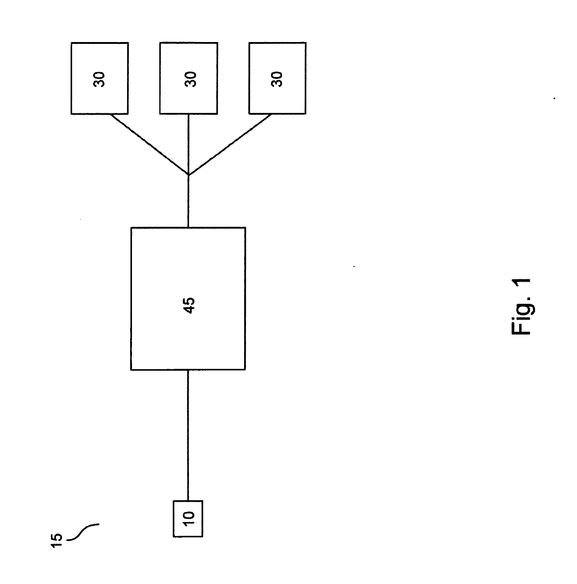
[0016] The invention is described with reference to the drawings. FIG. 1 illustrates the presently preferred embroidery network system architecture. The blocks in FIG. 1 illustrate components of an embroidery network system 15. The spatial layout and depiction of the system 15 in the drawings are done only for purposes of clarity and is simply one manner in which the various components of the network can be organized. It is to be therefore understood that the components and the functionalities described are not limited to any particular grouping, collection, or spatial relationship. Moreover, the components illustrated as part of the network may be in addition to other components, or to other functions and processes within the system 15, that are not described, or may be exclusive of other components.

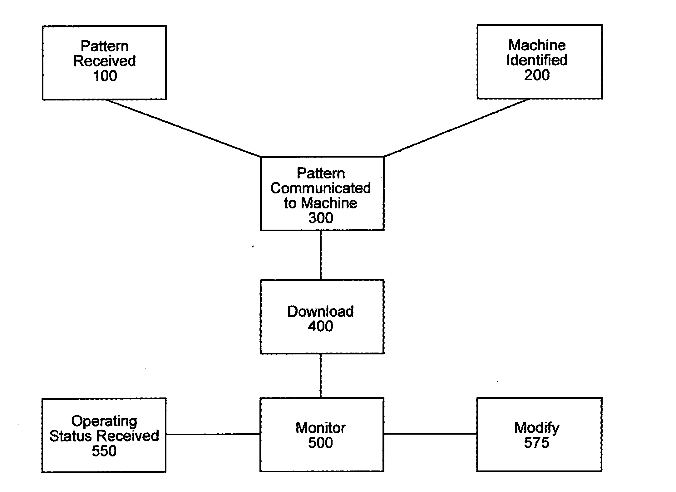
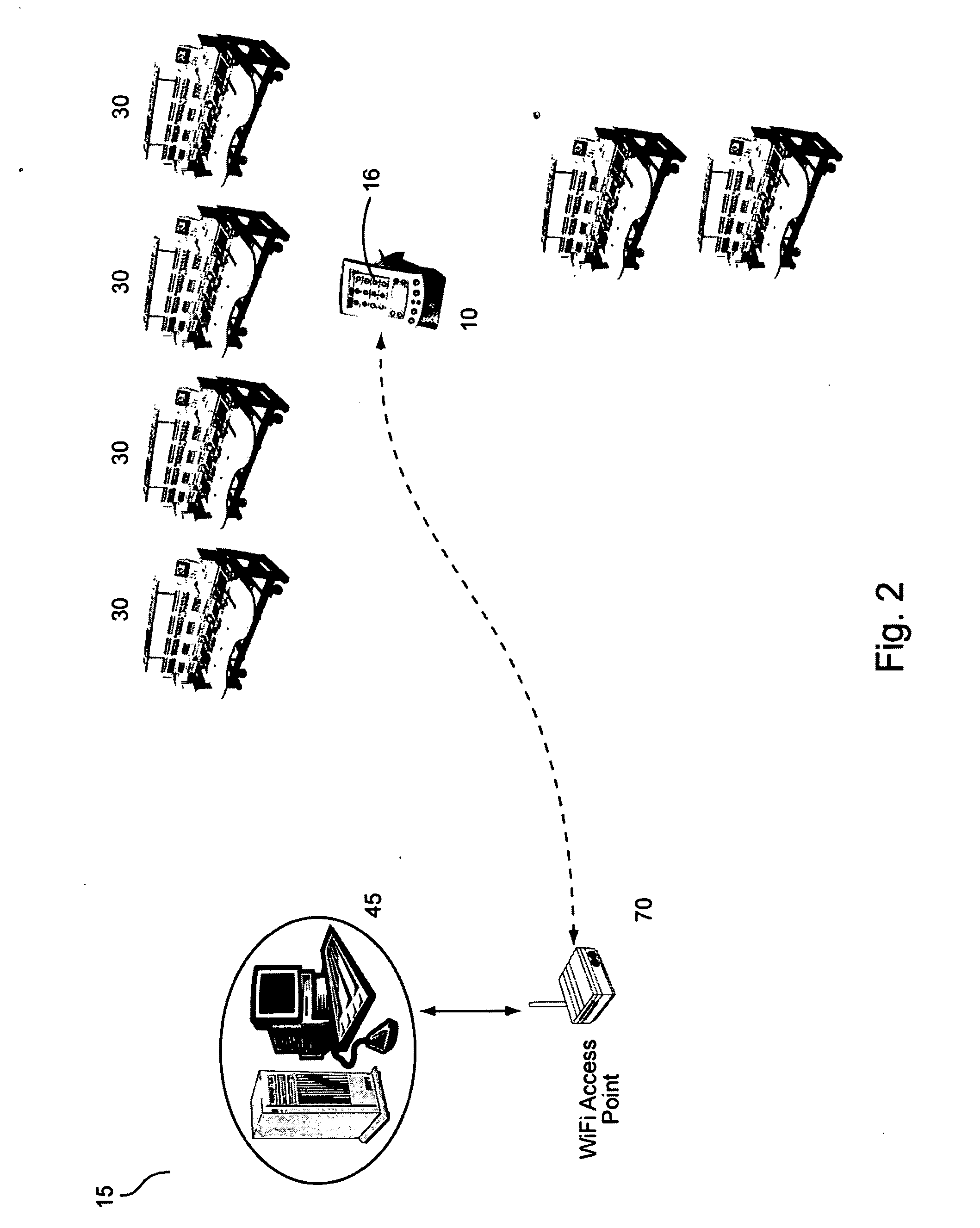
[0017] The invention allows a remote user to remotely send embroidery pattern designs to particular embroidery machinery for application of the embroidyer pattern to workpieces (e.g., ...


PUM


Abstract

A method and system of remotely communicating embroidery pattern data to embroidery machines involving providing an embroidery pattern in response to a pattern selection input from a remote user at a local node, the input communicated through a communications connection between the local node and a server, receiving an identification address for an embroidery machine, communicating the embroidery pattern to the embroidery machine for application of the embroidery pattern to a work piece. The system includes a server having circuitry for receiving wireless electronic communications, a local node having a graphical user interface for receiving input from a remote user, the local node in wireless electronic communication with the server, a database of electronically encoded data, the data comprising embroidery patterns, the database in communication with the server, and responsive to the local node input, to retrieve embroidery patterns and to display the embroidery patterns through the server to the remote user, and an embroidery machine in communication with the server, the embroidery machine receiving embroidery patterns from the database through the server.

Description

CLAIM TO PRIORITY [0001] This application claims the benefit of U.S. Provisional Application No. 60 / 472,493 filed on May 21, 2003, the application and its disclosure being incorporated herein by reference in their entirety for all purposes.FIELD OF THE INVENTION [0002] The present invention relates to embroidery systems and methods and particularly to implementing, controlling and monitoring the operation of embroidery systems from a remote source. BACKGROUND OF THE INVENTION [0003] Embroidery systems having an embroidery machine for automatically embroidering stitch patterns on a garment are well known in the art, including such systems employing microprocessor control to create customized embroidery patterns, such as disclosed in U.S. Pat. Nos. 6,012,402; 5,988,083; 5,865,134; 5,924,374; and 5,924,372. In addition, such prior art systems have employed an embedded ROM for the control software, such as disclosed in U.S. Pat. No. 5,586,134, as well as using removable ROM cards to sto...

Claims


Application Information

Patent Timeline
IPC IPC(8): D05B19/08D05C5/00
CPCD05C5/00D05B19/08
Inventor CAMERON, MARIONCARABENCIOV, IOANCOLLINS, WILLIAMDAVIS, WILLIAM J.GOLDBERG, BRIANRAO, MOHANTSONIS, ANASTASIOSWEST, CRAIG
Owner CAMERON MARION
Why Eureka
Try Eureka