
Computer systems

Inactive Publication Date: 2005-03-17
HEWLETT PACKARD DEV CO LP
View PDF12 Cites 5 Cited by
  • Summary
  • Abstract
  • Description
  • Claims
  • Application Information

AI Technical Summary

Benefits of technology

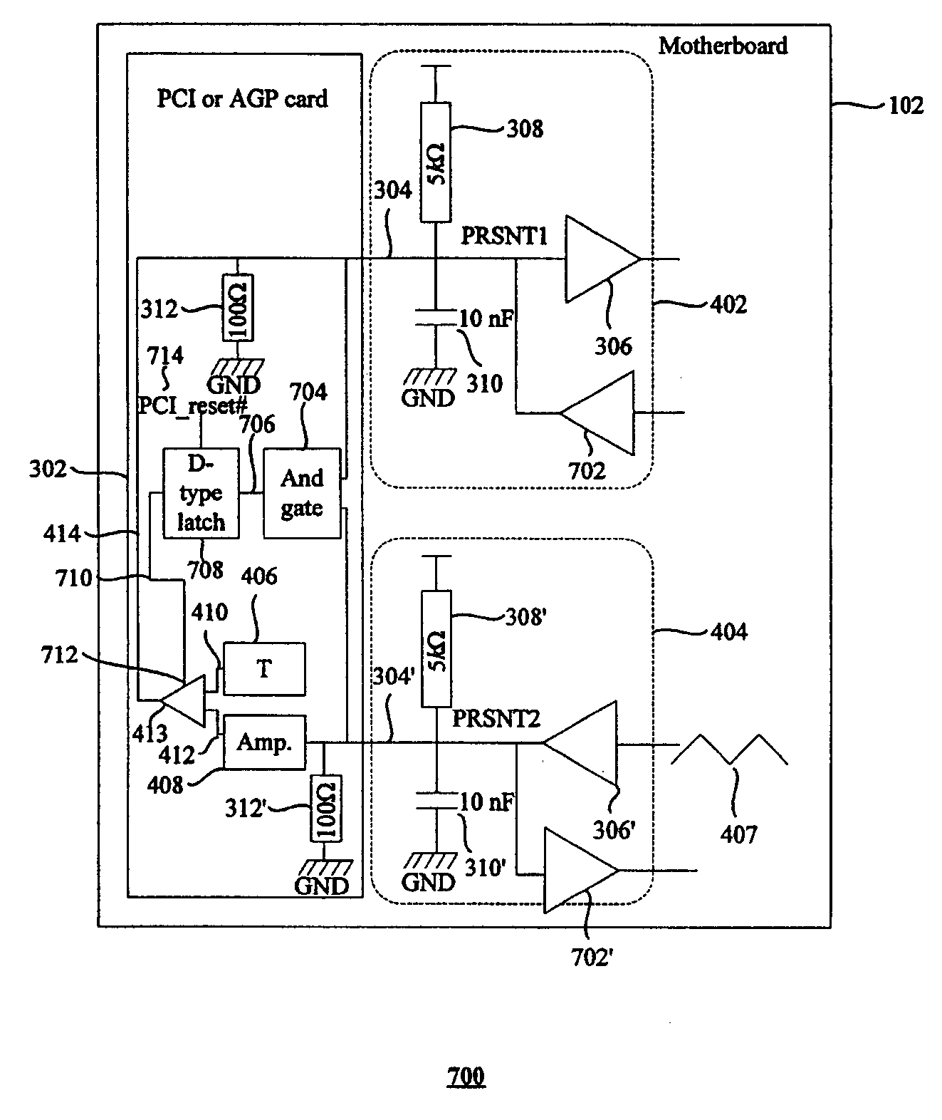
[0013] Advantageously, the current power consumption or cooling requirements of a card can be supplied to the PSU or the cooling system dynamically, that is, in a real-time manner. Therefore, the PSU can manage the power requirements, and, in turn, its own operation in light of the actual power requirements of the card or computer system. Alternatively or additionally, the cooling system can be used more efficiently since it can be arranged to respond to the actual cooling requirements of the computer system, that is, of any PCI or AGP cards that are present, rather than operating according to an anticipated maximum. It will be appreciated that additional benefits of embodiments of the present invention might include reduced acoustic noise and power saving, since the cooling system fan might be operating at a reduced level or a further power saving attributed to the PSU being operated according to actual power requirements rather than anticipated maximum power requirements.

Problems solved by technology

Since each card can consume, up to 25 Watts or add to the power budget for the PCI bus, adding such cards can impose an increased load on the PSU, which has associated power delivery issues, and also increase the cooling requirements imposed on the cooling system of the computer system.
However, the power consumption of such a high power video processor is unlikely to reach a full 25 W in all situations but for actually performing such computationally intensive 3-D rendering or the like.
Therefore, for example, when the computer system is being used to run a word processing application or is standing “idle”, the current video processing activities do not justify such a high level or onerous degree of cooling.
There are other PCI cards such as, for example, a RAID card, that exhibit high power consumption only during specific activities such as disc accesses.
As mentioned above, a significant limitation of the prior art is that the PCI 2.3 specification provides for the cards to supply an indication of their maximum power consumption requirements.
The specification does not accommodate dynamic changes in the actual power consumption or cooling requirements of those cards.

Method used


Image

  • Computer systems
  • Computer systems
  • Computer systems

Examples


Embodiment Construction

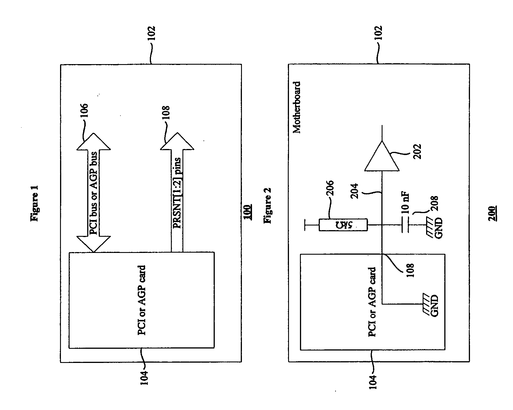
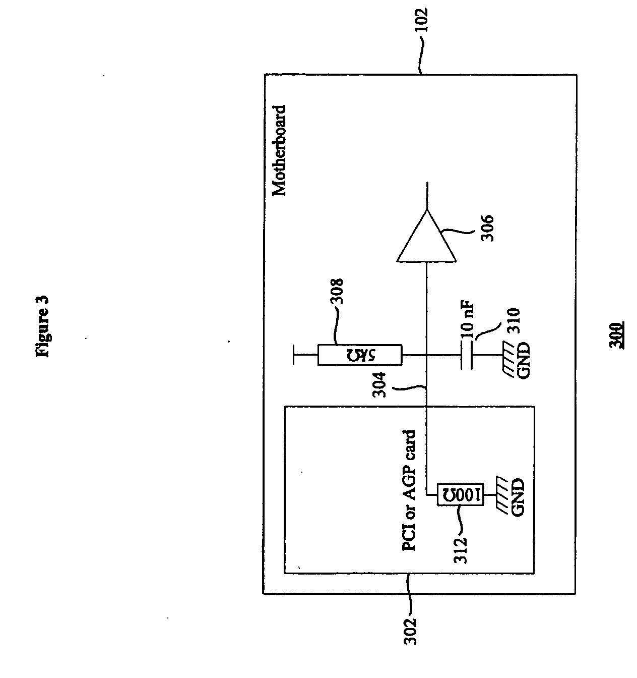
[0043]FIG. 3 shows the electrical assembly 300 of a PCI or AGP card according to an embodiment of the present invention and a motherboard 102. It will be appreciated that only one 304 of the PRSNT pins is illustrated rather than the two PRSNT [1:2] pins 108 shown in FIG. 1. This is for the purposes of clarity only. It will be appreciated that the circuit shown in FIG. 3 is equally applicable to both PRSNT pins. The pin 304 is connected to a respective buffer 306 that has its input connected to VCC via a 5 KΩ resistor 308 and is connected to ground via a 10 nF capacitor 310. Within, or on, the PCI or AGP card 302, the pin 304 is grounded via a 100 Ω resistor 312. Replacing the direct ground connection of the prior art PCI or AGP cards with a pull-down 100 Ω resistor achieves the same signalling effect as shown above in table 1 while concurrently allowing a further signal to be transmitted via the pin 304. Therefore, embodiments of the present invention, rather than leaving the pin 30...


PUM


Abstract

The present invention relates to computer systems. An embodiment provides an arrangement for a computer system; the arrangement comprising at least one terminal to provide dynamic information relating to an operating characteristic of the arrangement; and circuitry, using the at least one terminal, to produce an output signal bearing the dynamic information associated with the operating characteristic of the arrangement.

Description

FIELD OF THE INVENTION [0001] The present invention relates to computer systems and, more particularly, to computer systems incorporating, for example, power or cooling management. BACKGROUND TO THE INVENTION [0002] Computers can be configured according to a myriad of configuration possibilities. These configurations encompass entry level configurations with almost no add-in cards in situ or a heavy, or fully loaded, configuration that might accommodate a significant number of PCI or AGP cards. Since each card can consume, up to 25 Watts or add to the power budget for the PCI bus, adding such cards can impose an increased load on the PSU, which has associated power delivery issues, and also increase the cooling requirements imposed on the cooling system of the computer system. [0003] The PCI SIG organisation introduced two pins, PRSNT [1:2], on each card to allow that card to signal to the motherboard, and, ultimately, the cooling system or power supply, its maximum power or cooling...

Claims


Application Information

Patent Timeline
IPC IPC(8): G06F1/20G06F3/00G06F11/30G06F13/40H05K7/20
CPCG06F1/206G06F11/3031Y02B60/1275G06F11/3062G06F11/3065G06F11/3058Y02D10/00
Inventor MEYNARD, OLIVIERGRECO, DAVID
Owner HEWLETT PACKARD DEV CO LP
Learn More