
Language for performing high level actions using hardware registers

a hardware register and high-level technology, applied in the field of utilizing a common hardware representation language, can solve the problems of large software development time, limited hardware specific device drivers, and inability to meet the requirements of hardware specific device drivers, and achieve the effect of facilitating the use of a common hardware driver

Inactive Publication Date: 2005-03-17
MICROSOFT TECH LICENSING LLC
View PDF8 Cites 159 Cited by
  • Summary
  • Abstract
  • Description
  • Claims
  • Application Information

AI Technical Summary

Benefits of technology

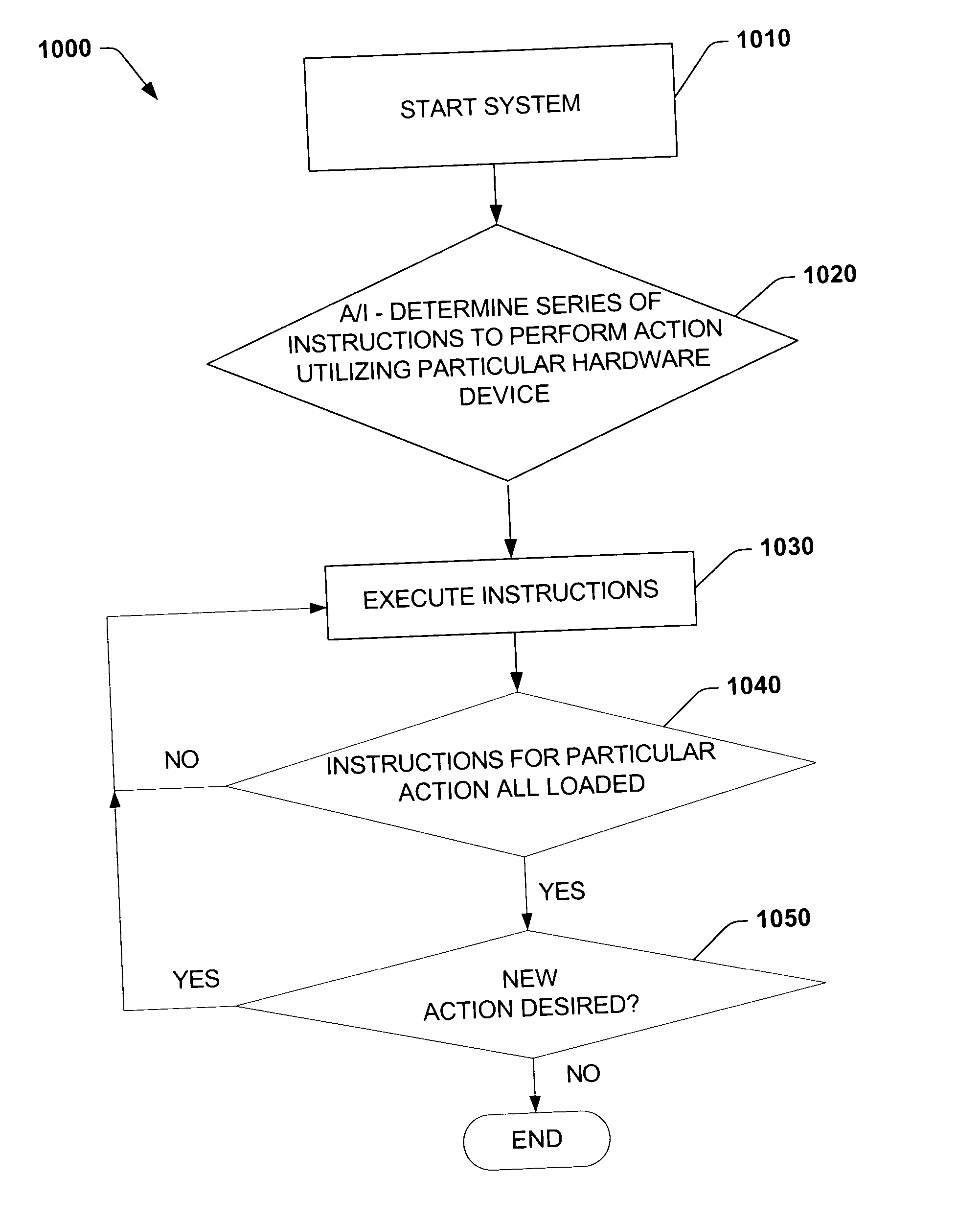
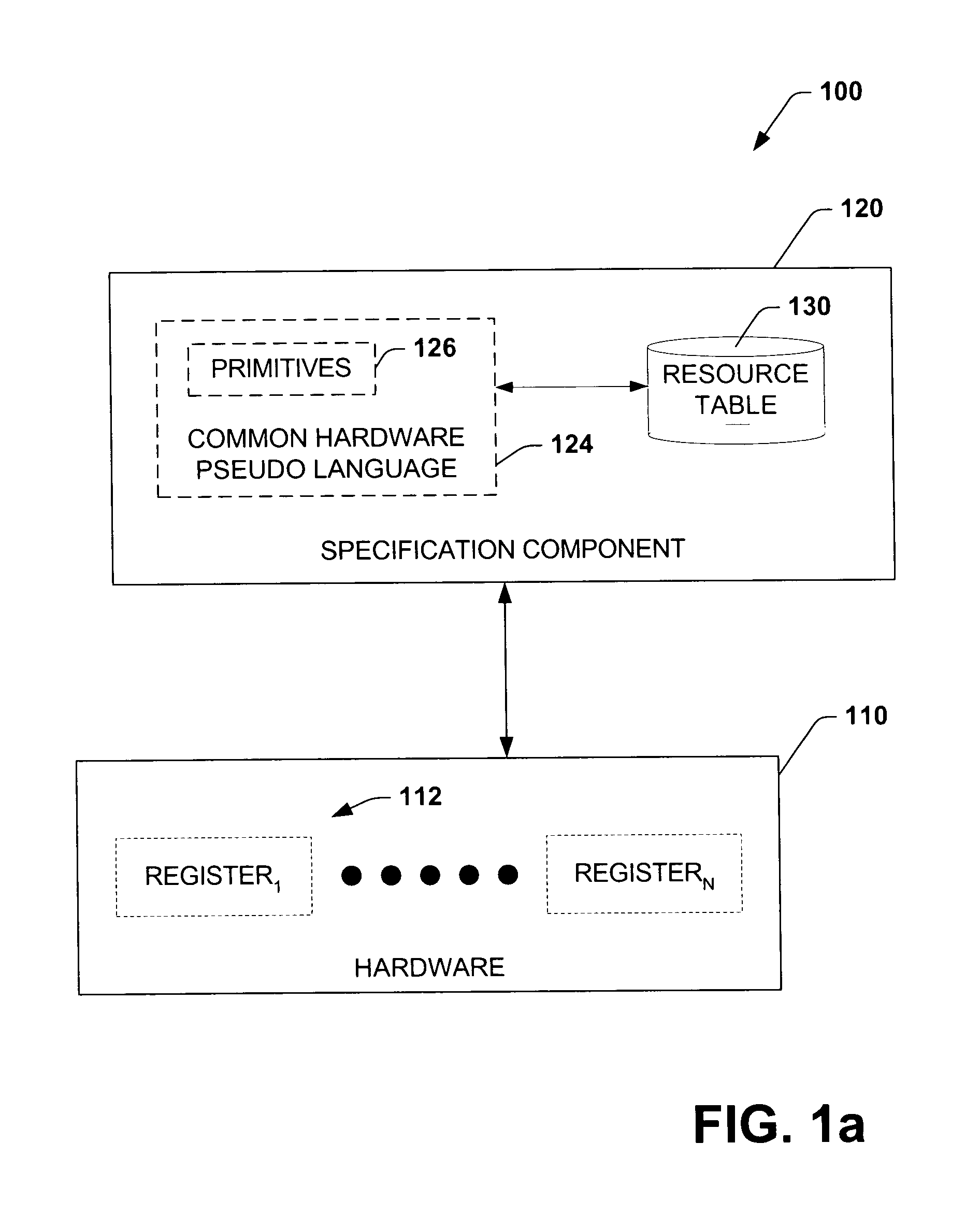
The present invention provides a system and method for utilizing a common hardware representation language to describe hardware functionality and execute hardware actions. This language abstracts device resources, making it easier to develop software for a device class. The invention facilitates the use of a common hardware driver to support unique functionality of the hardware device and the functionality can be utilized prior to operating system kernel availability. The technical effects of the invention include improved efficiency in software development and flexibility in hardware functionality.

Problems solved by technology

Numerous limitations result from the need for hardware specific device drivers.
High costs are often associated with developing hardware specific device drivers, extensive software development time can be required to develop software capable of employing unique hardware functionalities, hardware development and utilization typically is slowed by unavailability of software capable of taking advantage of unique features of the hardware initially when new hardware functionalities are created, and software development can be slowed because the software must conform with requirements of the hardware.
Another shortcoming of conventional register based hardware is that hardware can be inaccessible prior to operating system kernel availability because a hardware specific device driver is required to interact with the device.
Such limitation can render the hardware unusable for applications, such as, for example, a watchdog timer implemented to detect and respond to system failures prior to boot up and during initialization.
Furthermore, systems and methods are lacking which are extensible to enable utilization of additional features in future hardware.

Method used


Image

  • Language for performing high level actions using hardware registers
  • Language for performing high level actions using hardware registers
  • Language for performing high level actions using hardware registers

Examples


Embodiment Construction

[0024] The present invention is now described with reference to the drawings, wherein like reference numerals are used to refer to like elements throughout. In the following description, for purposes of explanation, numerous specific details are set forth in order to provide a thorough understanding of the present invention. It may be evident, however, that the present invention may be practiced without these specific details. In other instances, well-known structures and devices are shown in block diagram form in order to facilitate describing the present invention.

[0025] As used in this application, the terms “component” and “system” are intended to refer to a computer-related entity, either hardware, a combination of hardware and software, software, or software in execution. For example, a component may be, but is not limited to being, a process running on a processor, a processor, an object, an executable, a thread of execution, a program, and / or a computer. By way of illustrat...


PUM


Abstract

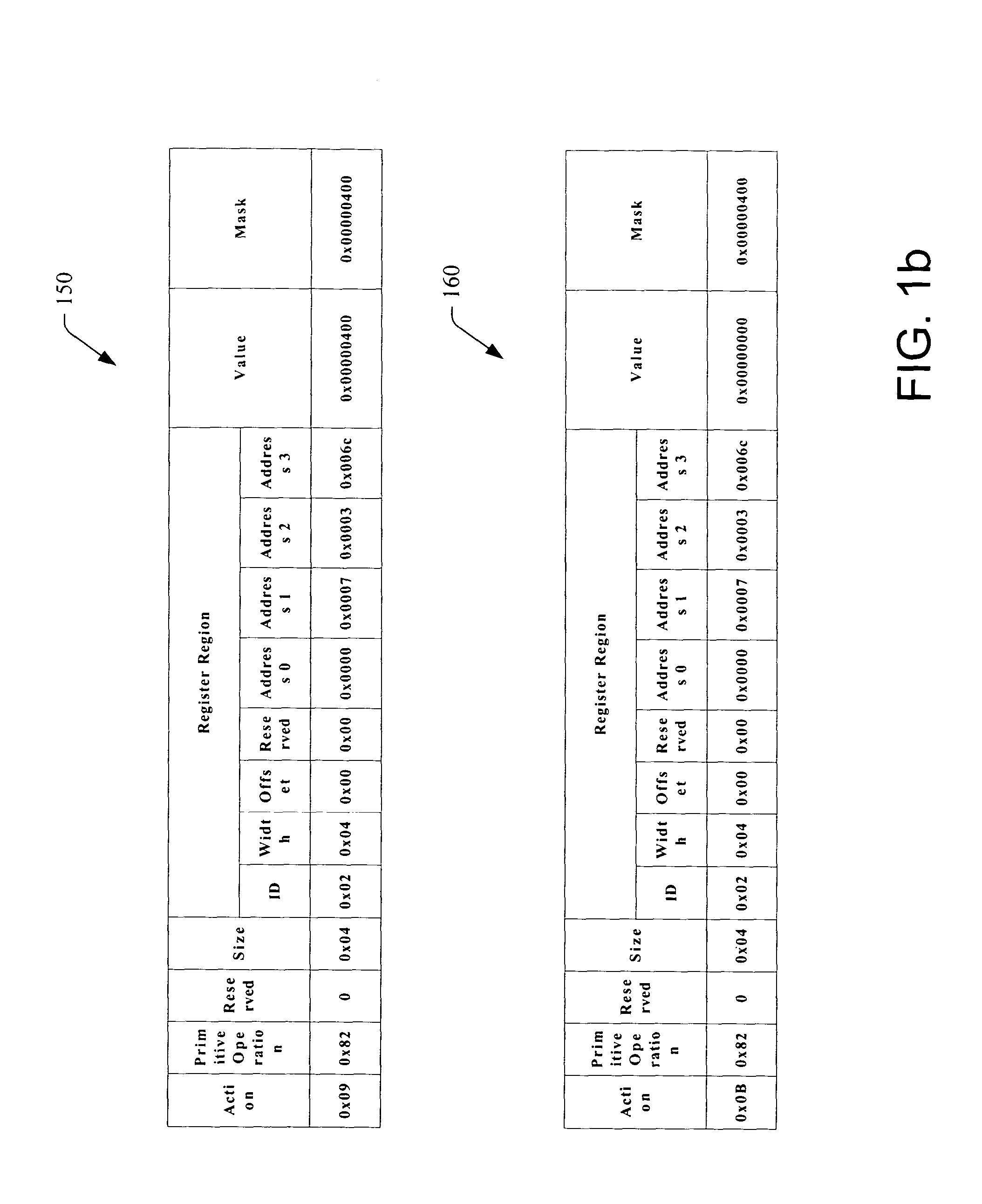
A system and method that utilizes a common hardware register pseudo-language are disclosed. The present invention employs a common platform to specify hardware functionality and to execute hardware action(s). Hardware actions can be effectuated by performing a series of instructions, which comprise hardware register primitives and resources utilized by the primitives. The hardware register primitives are operations defined according to the common hardware register pseudo-language. The series of instructions can be loaded prior to boot or during initialization.

Description

TECHNICAL FIELD [0001] The present invention relates generally to utilizing a common hardware representation language, and more particularly to systems and methods that can utilize a common hardware register representation language to specify hardware functionality. BACKGROUND OF THE INVENTION [0002] In the computer hardware industry, there is a trend to develop devices with unique functionality. For example, hardware vendors seek to incorporate unique (e.g., proprietary) features to differentiate their device(s) from that of competitors. For example, even though register-based devices (e.g., debugger port, EMS port, system timer, interrupt controller, bus controller, . . . ) employ hardware registers for communication and control, such devices can utilize the hardware registers in disparate manners depending on the vendor's design specification. Resources of register based devices include I / O, memory mapped or Configuration Registers. Register(s) can be physically located within th...

Claims


Application Information

Patent Timeline
Patent Type & Authority Applications(United States)
IPC IPC(8): G06F9/445G06F15/177
CPCG06F9/4411
Inventor SCHWARTZ, JAMES A. JR.PLANTE, STEPHANE G.NELSON, ROBERT B.
Owner MICROSOFT TECH LICENSING LLC
Learn More