Internal combustion engine ignition apparatus
a technology of ignition apparatus and internal combustion engine, which is applied in the direction of ignition automatic control, electric control, machines/engines, etc., can solve the problems of affecting the timing, degrading the ignition characteristic, and the reference potential level of the ignition signal voltage disturbing the timing, so as to avoid the degradation of the ignition characteristic and simplify the terminal structure
- Summary
- Abstract
- Description
- Claims
- Application Information
AI Technical Summary
Benefits of technology
Problems solved by technology
Method used
Image
Examples
embodiment 1
[0030] Embodiment 1
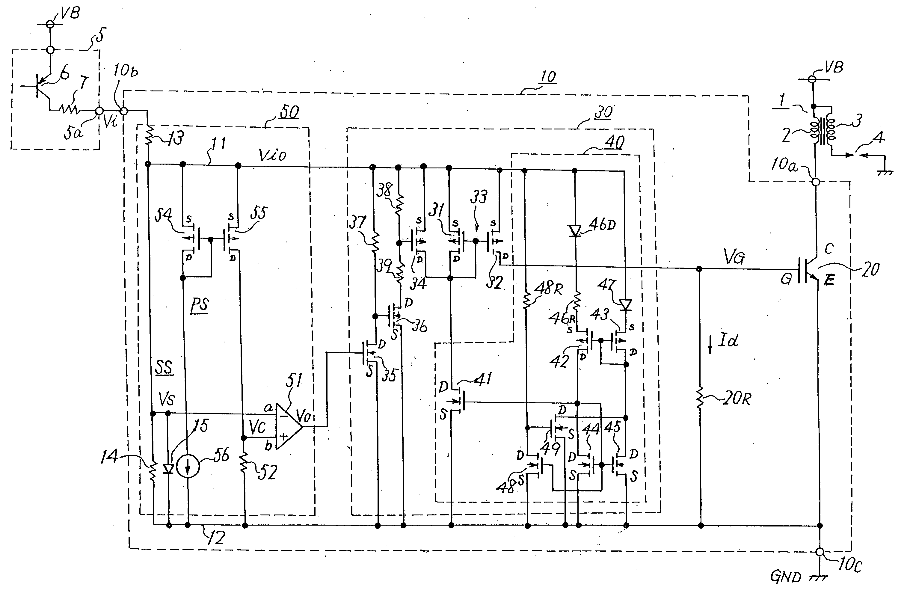
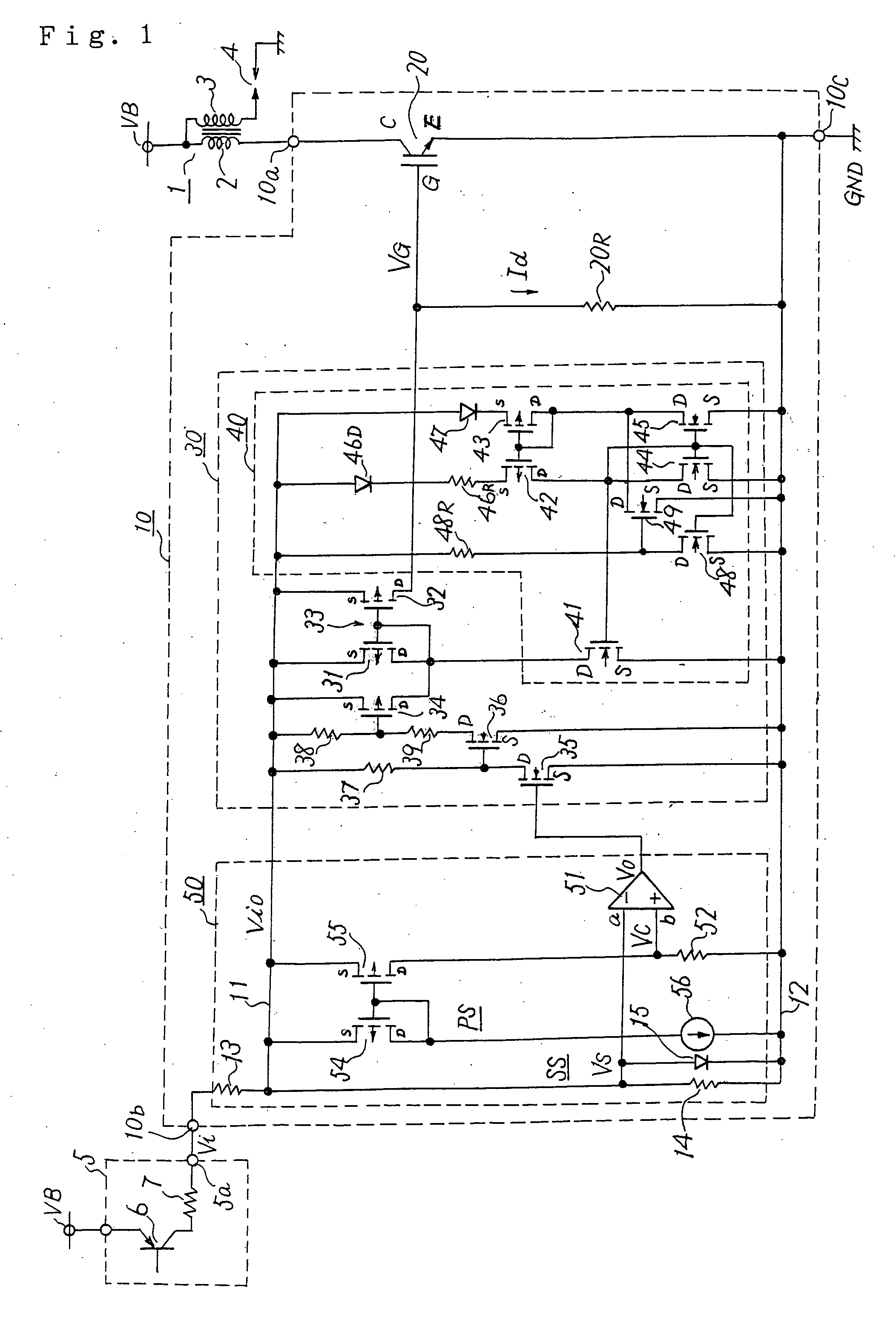
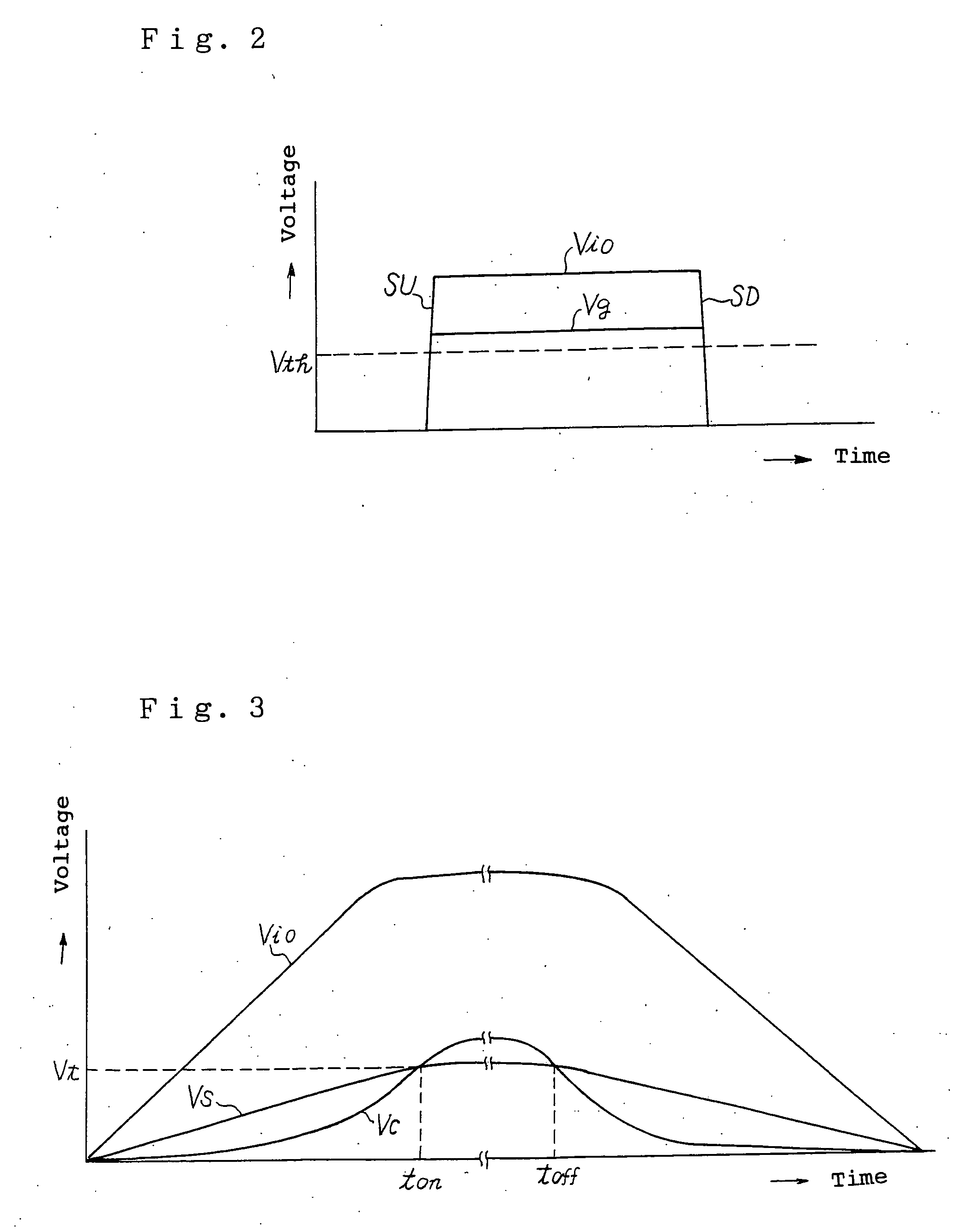
[0031]FIG. 1 shows embodiment 1 of an internal combustion engine ignition apparatus of the invention. FIGS. 2 and 3 are characteristic diagrams for explaining the operation of the embodiment 1.
[0032] The internal combustion engine ignition apparatus of the embodiment 1 is an ignition apparatus for an internal combustion engine mounted in an automobile, and includes an ignition coil 1, an ignition driving circuit 5, and a switching circuit 10. The ignition coil 1 includes a primary coil 2 and a secondary coil 3 and is connected to a power supply terminal VB such as an on-board battery. The on-board battery has, for example, 12 volts, and the power supply terminal VB has, for example, 12 volts. A spark plug 4 is connected to the secondary coil 3. This spark plug 4 is disposed in a combustion chamber of the internal combustion engine, and ignites fuel, such as gasoline, supplied into the combustion chamber to burn it.
[0033] The ignition driving circuit 5 is include...
embodiment 2
[0061] Embodiment 2
[0062]FIG. 4 shows embodiment 2 of an internal combustion engine ignition apparatus of the invention, and FIG. 5 is an explanatory diagram of the operation of the embodiment 2.
[0063] The embodiment 2 shown in FIG. 4 includes a switching circuit 10A. The switching circuit 10A is constructed by three terminals, that is, an output terminal 10a, an input terminal 10b and a reference potential terminal 10c similarly to the switching circuit 10 shown in FIG. 1. The input terminal 10a is directly connected to a primary coil 2 of an ignition coil 1, the input terminal 10b is directly connected to an ignition signal terminal 5a of an ignition driving circuit 5, and the reference potential terminal 10c is directly connected to a reference potential point GND.
[0064] This switching circuit 10A includes a waveform shaping circuit 50A instead of the waveform shaping circuit 50 of FIG. 1, and in this embodiment 2, instead of the ignition signal line 11 of FIG. 1, an ignition s...
embodiment 3
[0076] Embodiment 3
[0077]FIG. 6 shows embodiment 3 of an internal combustion engine ignition apparatus of the invention. This embodiment 3 uses a switching circuit 10B. The switching circuit 10B is such that a current limiting circuit 60 is added to the switching circuit 10 of the embodiment 1 shown in FIG. 1. Along with this, instead of the switching element 20 shown in FIG. 1, a switching element 20A having an auxiliary emitter E1 is used. Since the others are constructed similarly to the embodiment 1 of FIG. 1, the same parts are denoted by the same symbols and the explanation will be omitted. Incidentally, in this embodiment 3, the waveform shaping circuit 50A shown in FIG. 4 is used.
[0078] The switching element 20A is an IGBT, and this includes a collector C, a main emitter E, the auxiliary emitter E1, and a gate G. The collector C is directly connected to an output terminal 10a of the switching circuit 10B, and the main emitter E is directly connected to a reference potential...
PUM
 Abstract
Description
Claims
Application Information
 - R&D
- Intellectual Property
- Life Sciences
- Materials
- Tech Scout
- Unparalleled Data Quality
- Higher Quality Content
- 60% Fewer Hallucinations
Browse by: Latest US Patents, China's latest patents, Technical Efficacy Thesaurus, Application Domain, Technology Topic, Popular Technical Reports.
© 2025 PatSnap. All rights reserved.Legal|Privacy policy|Modern Slavery Act Transparency Statement|Sitemap|About US| Contact US: help@patsnap.com


