
Apparatus for the electrostatic separation of particulate mixtures

Inactive Publication Date: 2005-03-24
ORE KINETICS INVESTMENTS
View PDF22 Cites 8 Cited by
  • Summary
  • Abstract
  • Description
  • Claims
  • Application Information

AI Technical Summary

Benefits of technology

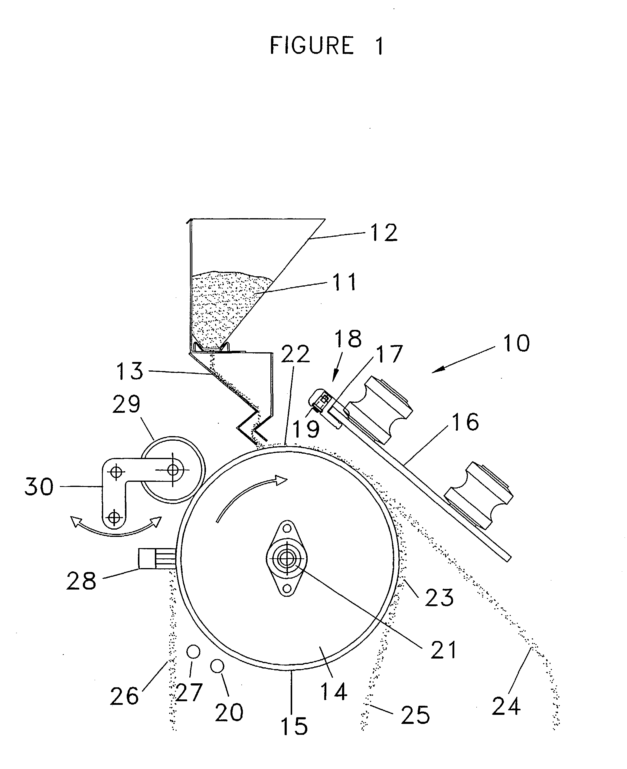
[0022] It will be appreciated that the first static electrode ordinarily has its leading edge closely adjacent the ionising electrode, and preferably has its leading edge located behind the ionising electrode with respect to the conductive surface. This ensures that the static electric field generated by the first static electrode acts continuously upon the ionised particles both during and after the ionising process. This, in turn, ensures that there is a repelling action on all particles, both conducting and non-conducting, tending to force them back onto the conductive surface. Accordingly, particle bounce is minimised and particle contact with the conductive surface is maximised. As a result, the maximum opportunity for conducting particles to discharge their charge to the conductive surface is provided, and therefore separation of conducting and non-conducting particles is enhanced. This effect is most pronounced with the larger and heavier non-conductors since these are most likely to bounce off the conductive surface and consequently misreport to the conductor stream. However, since these particles still carry most of the charge attained when ionised they are continuously repelled by the first static electrode and therefore substantially less likely to join the conductor stream.
[0048] However, in addition, it has been found that conventional electrostatic separators have a propensity for the conductive surface to attract and become coated with non-conductive organic or inorganic film after hours or days of operation. As good electrical contact between the particles and the conductive roll surface is highly desirable, it is preferred that the apparatus further comprise cleaning means for cleaning the conductive surface. Since the cleaning means is generally an abrasive brush or pad, it is desirable that it contact the conductive surface only intermittently. A typical cleaner is a rotating abrasive linish roll, but an abrasive wire brush or an abrasive cloth or any other conventional cleaner for such surfaces may be used. It is desirable that the abrasive cleaner only be used for short periods, as continuous contact may result in rapid erosion of the conductive surface.

Problems solved by technology

This effect is most pronounced with the larger and heavier non-conductors since these are most likely to bounce off the conductive surface and consequently misreport to the conductor stream.
However, since these particles still carry most of the charge attained when ionised they are continuously repelled by the first static electrode and therefore substantially less likely to join the conductor stream.

Method used


Image

  • Apparatus for the electrostatic separation of particulate mixtures
  • Apparatus for the electrostatic separation of particulate mixtures
  • Apparatus for the electrostatic separation of particulate mixtures

Examples


Embodiment Construction

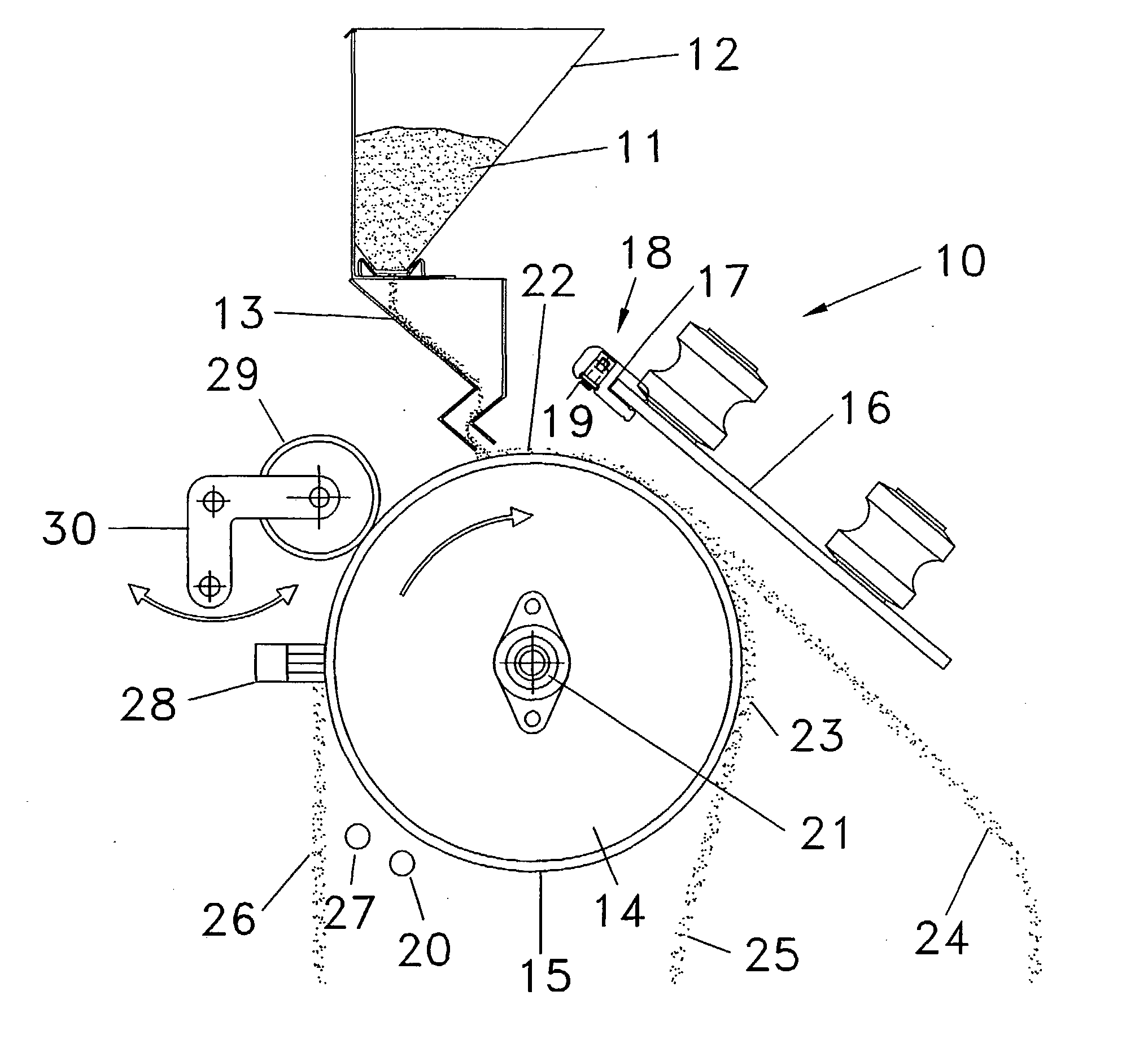
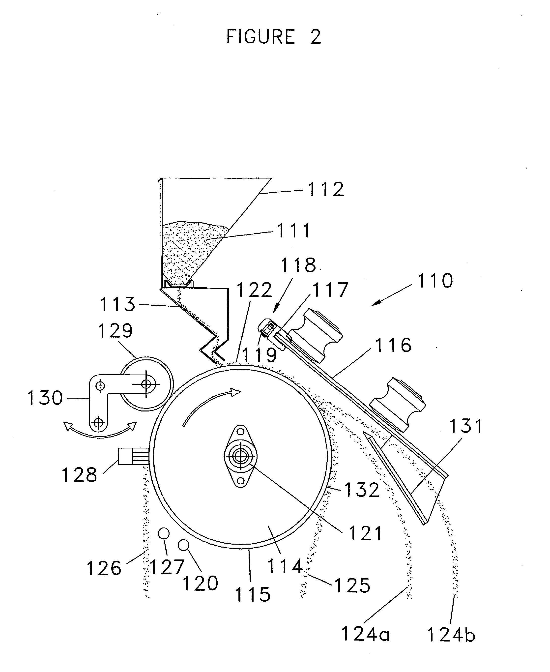
[0070] The apparatus 10, 110, 210, 310, 410 and 510 shown in FIGS. 1, 2, 3, 5, 6 and 8, respectively, is a particle separator used to separate particulate mixtures comprising species that exhibit difference in electrical conductivity. In particular, the apparatus serves to separate electrically conducting species from non-conducting species on the basis of their differing capacities to retain charge in a roll-type electrostatic separator. The devices are substantially similar and therefore the overall operation shall be described with reference to FIG. 1 only, and variations shall be described with reference to FIGS. 2 to 8. In view of the similarity of the devices, reference numerals in FIGS. 2 to 8 will be the same as those in FIG. 1 for similar features, except that the features will be numbered from 110, 210, 310, 410 and 510 in FIGS. 2, 3, 4, 5, 6 and 8, respectively.

[0071] Referring to FIG. 1, a mixture of particulate material 11 is contained within hopper 12 and fed via a fe...


PUM


Abstract

Apparatus for the electrostatic separation of a mixture of particles that exhibit difference in electrical conductivity, comprising: a conductive surface to which conducting particles lose their charge; feeding means for feeding the mixture of particles onto the conductive surface; an ionising electrode for ionising individual particles in the mixture of particles; and a first static electrode having the same polarity as the ionising electrode and which serves to generate a static electric field, the first static electrode being located sufficiently close to the ionising electrode that the static electric field acts continuously on the particles as they are ionised; wherein conducting particles are separated from non-conducting particles on the basis of their different retained charge after a period of contact with the conductive surface.

Description

TECHNICAL FIELD [0001] The present invention is concerned with a particle separator for the separation of particulate mixtures comprising species that exhibit difference in electrical conductivity and, more particularly, with the separation of particulate mixtures comprising species that exhibit difference in electrical conductivity through electrostatic separation. BACKGROUND ART [0002] Mineral separation plants used in the titanium mineral processing industry world-wide consist essentially of similar process technologies applied in a manner that is often tailored to an individual ore bodies separation requirements. Dependent upon a wide number of factors including particle size and shape, mineral grade, geology of the ore body, type of mineral species present and the physical characteristics of said mineral species, a unique recovery process is applied to optimise plant performance and satisfy operational and capital cost targets. Nevertheless, all titanium mineral processing plan...

Claims


Application Information

Patent Timeline
IPC IPC(8): B03C7/02B03C7/06
CPCB03C7/06B03C7/02
Inventor GATES, PETER J.
Owner ORE KINETICS INVESTMENTS
Learn More