Nanopowder synthesis using pulsed arc discharge and applied magnetic field

a technology of pulsed arc discharge and magnetic field, applied in the direction of manufacturing tools, electric/magnetic/electromagnetic heating, oxygen/ozone/oxide/hydroxide, etc., can solve the problems of arc discharge, non-uniform quality of material produced, and production rate reduction

Active Publication Date: 2005-03-24
NCC NANO LLC
View PDF26 Cites 49 Cited by
  • Summary
  • Abstract
  • Description
  • Claims
  • Application Information

AI Technical Summary

Problems solved by technology

A reoccurring problem in the above prior art systems is that the arc discharge may occur from time to time at other than ...

Method used


Image

  • Nanopowder synthesis using pulsed arc discharge and applied magnetic field
  • Nanopowder synthesis using pulsed arc discharge and applied magnetic field
  • Nanopowder synthesis using pulsed arc discharge and applied magnetic field

Examples


Embodiment Construction

in conjunction with the following drawings, in which:

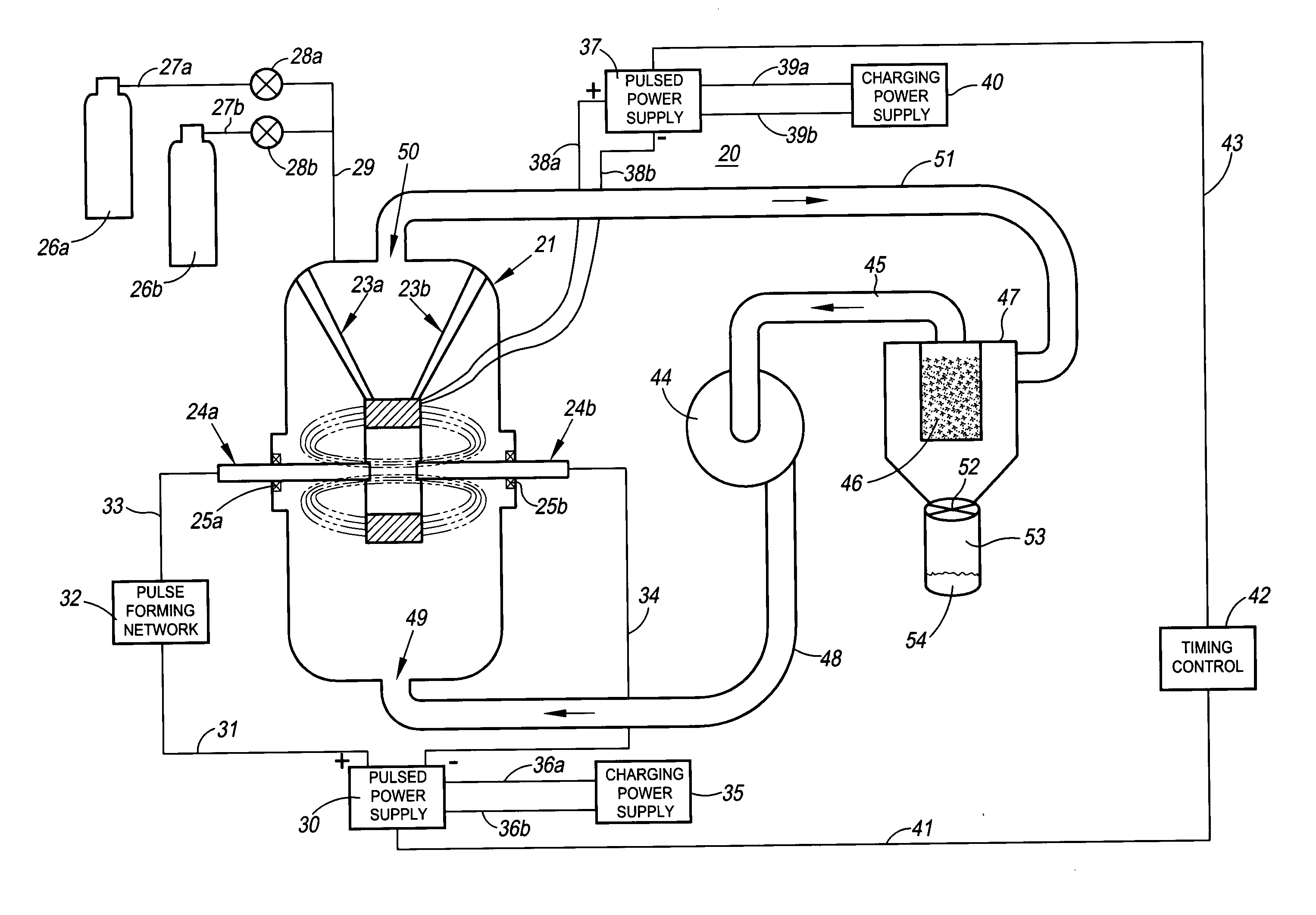
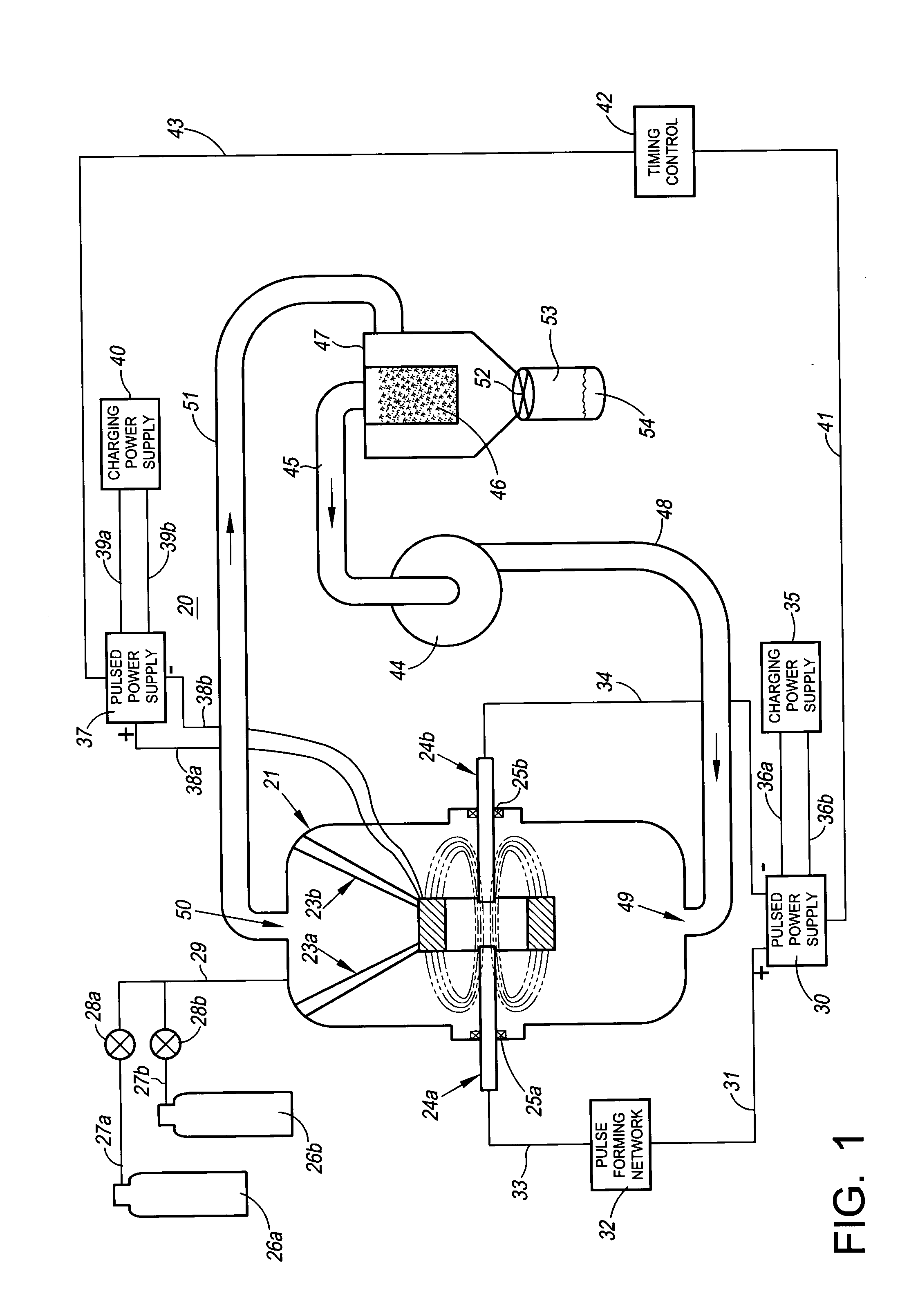
[0009]FIG. 1 is a functional block diagram of a nanopowder synthesis system in accordance with the invention;

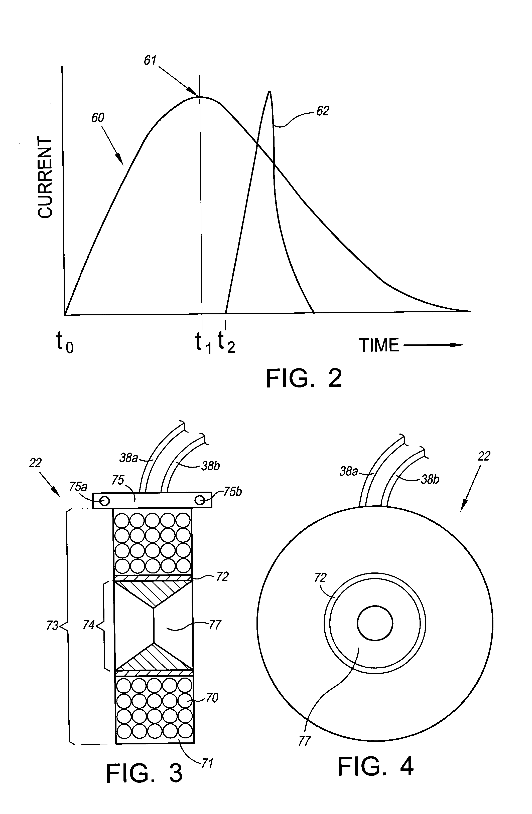
[0010]FIG. 2 is a graph showing the discharge currents generated by the pulsed power supply 30 and the pulsed power supply 37 of FIG. 1 above;

[0011]FIG. 3 is a cross-sectional view of a solenoid magnet used in the preferred embodiment of the invention illustrated in FIG. 1 above;

[0012]FIG. 4 is a side view of the solenoid magnet of FIG. 3 above with a central insert;

[0013]FIG. 5 is a graph showing the relation of electrode ablation rate to magnet power supply voltage;

[0014]FIG. 6 is a graph showing the relation of nanopowder yield to magnet power supply voltage;

[0015]FIG. 7 is taken from a Transmission Electron Microscope (TEM) image of nanopowder produced with the magnet of FIG. 4 above having a polycarbonate insert;

[0016]FIG. 8 is taken from a TEM image of nanopowder produced with the magnet of FIG. 4 above having ...


PUM

PropertyMeasurementUnit
Poweraaaaaaaaaa
Diameteraaaaaaaaaa
Magnetic fieldaaaaaaaaaa

Abstract

Nanopowder synthesis systems in which a pulsed magnetic field is applied to electrodes of precursor material, in close proximity to an electrical discharge arc that is formed between the electrodes, to attain increased yields of nanopowder. A magnet insert of a coating precursor material is used to coat the nanopowder and thereby reduce nanoparticle agglomeration.

Description

RELATED PATENT APPLICATION [0001] U.S. patent application Ser. No. 10 / 455,292 filed on Jun. 5, 2003, entitled “Radial Pulsed Arc Discharge Gun For Synthesizing Nanopowders”, having Kurt Schroder and Doug Jackson as inventors, and assigned to the assignee of the present invention.FIELD OF THE INVENTION [0002] The invention relates generally to nanopowder synthesis processes, and more particularly to the use of an applied magnetic field to significantly increase nanopowder production rates resulting from a synthesis process. BACKGROUND OF THE INVENTION [0003] Plasma based systems for synthesizing nanopowders are disclosed in U.S. Pat. Nos. 5,514,349; 5,874,684; and 6,472,632. The axial electrothermal gun embodiment disclosed in U.S. Pat. No. 6,472,632 is an improvement over the plasma based synthesis systems of the '349 and '684 patents. The '632 system uses a high powered pulsed arc discharge in combination with an axial electrothermal gun to attain a higher temperature and higher de...

Claims


Application Information

Patent Timeline
IPC IPC(8): B01J19/08B23K10/00
CPCB01J19/088B01J2219/0809B01J2219/0822B01J2219/083B01J2219/0839B01J2219/0854B01J2219/0862B22F2999/00B22F9/14B01J2219/0886B01J2219/0898B22F3/003B82B3/00B23K10/00C01B13/28
Inventor SCHRODER, KURT A.JACKSON, DOUG K.
Owner NCC NANO LLC
Why Eureka
Try Eureka