Wire bonding method and apparatus

a wire bonding and wire technology, applied in the direction of soldering apparatus, manufacturing tools,auxillary welding devices, etc., can solve the problems of poor bonding properties and the inability to judge the situation of “bump not adhered” in a normal fashion, and achieve the effect of improving productivity

Active Publication Date: 2005-03-24
SHINKAWA CO LTD
View PDF7 Cites 16 Cited by
  • Summary
  • Abstract
  • Description
  • Claims
  • Application Information

AI Technical Summary

Benefits of technology

[0020] The object of the present invention is to provide a wire bonding method and apparatus that requires no external appearance inspection for all of the devices produced and that detects a “bump not-adhered” situation during wire bonding, thus improving the productivity.

Problems solved by technology

However, to the second conductor, since the wire without a ball is bonded as a secondary bonding, the joining properties are poor compared to the joining properties of the primary bonding.
Accordingly, there is a danger that a “bump not-adhered” situation cannot be judged in a normal fashion.

Method used


Image

  • Wire bonding method and apparatus
  • Wire bonding method and apparatus
  • Wire bonding method and apparatus

Examples


Embodiment Construction

[0029] One embodiment of the present invention will be described with reference to FIGS. 1 and 2. Members that are the same as in FIGS. 3(a) through 5 or that correspond to those in FIGS. 3(a) through 5 are labeled with the same symbols, and a detailed description of such members is omitted.

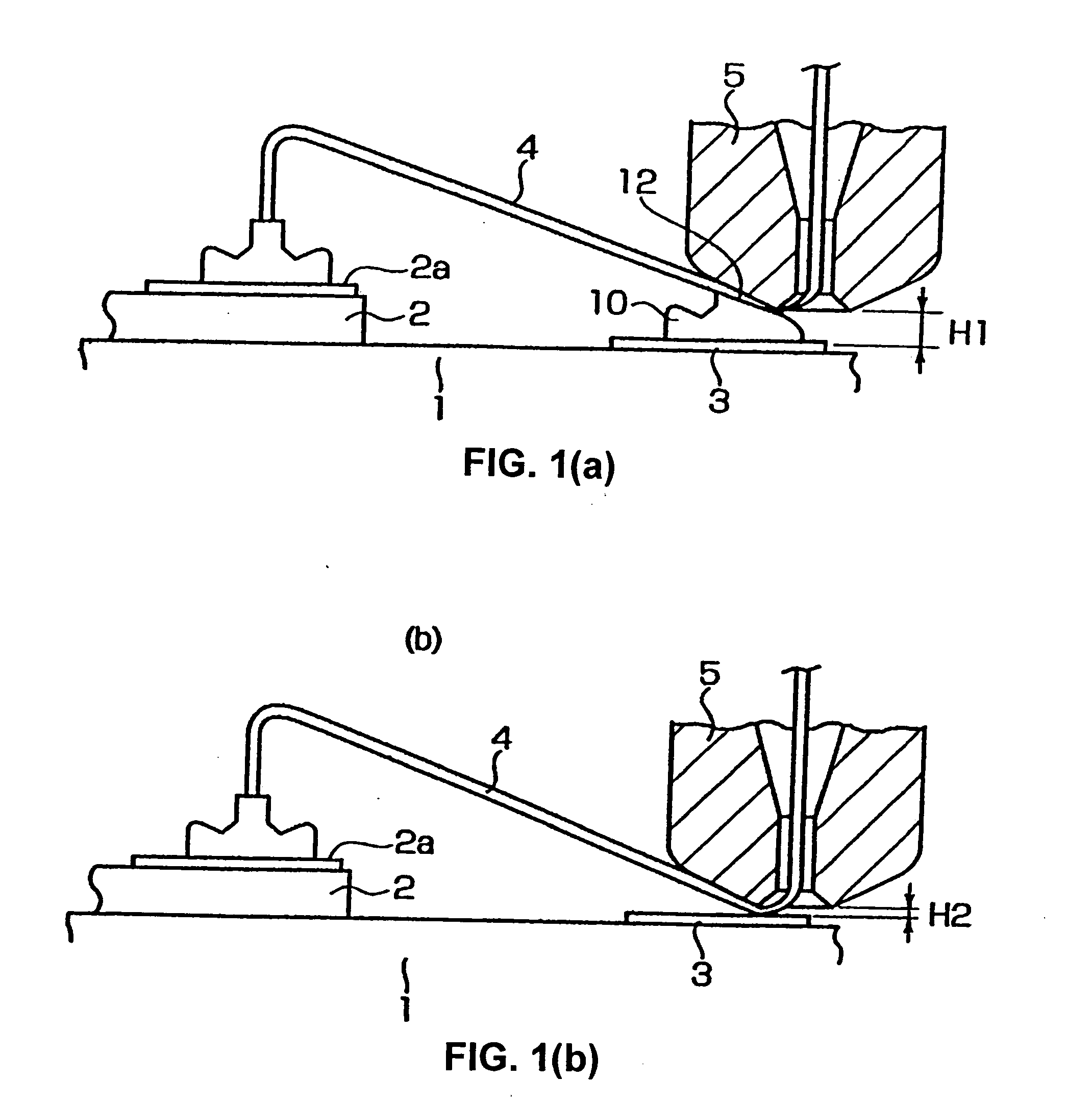
[0030]FIG. 1(a) shows the same state as in FIG. 3(b). First, the operation described below is performed prior to the wire bonding operation.

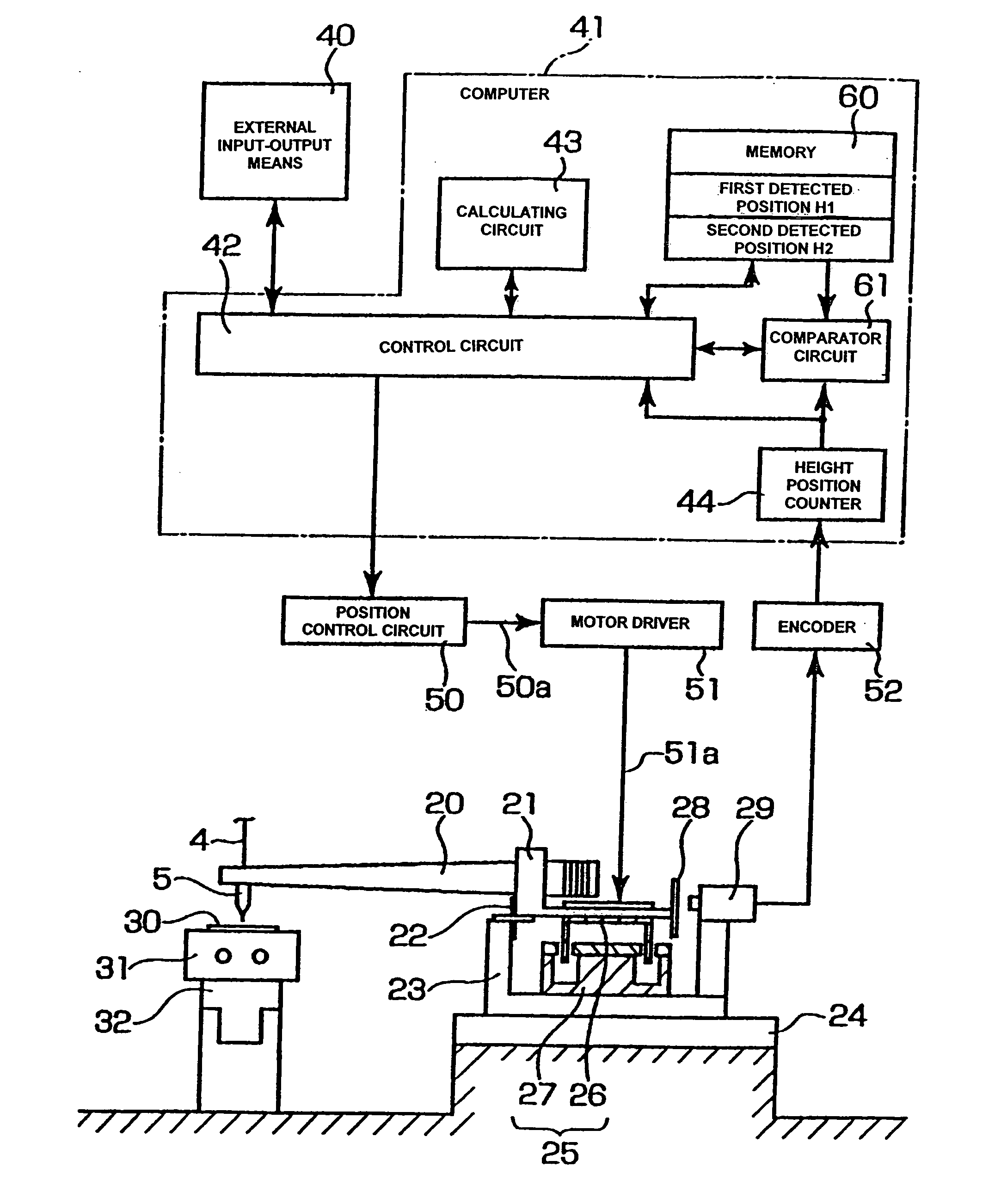
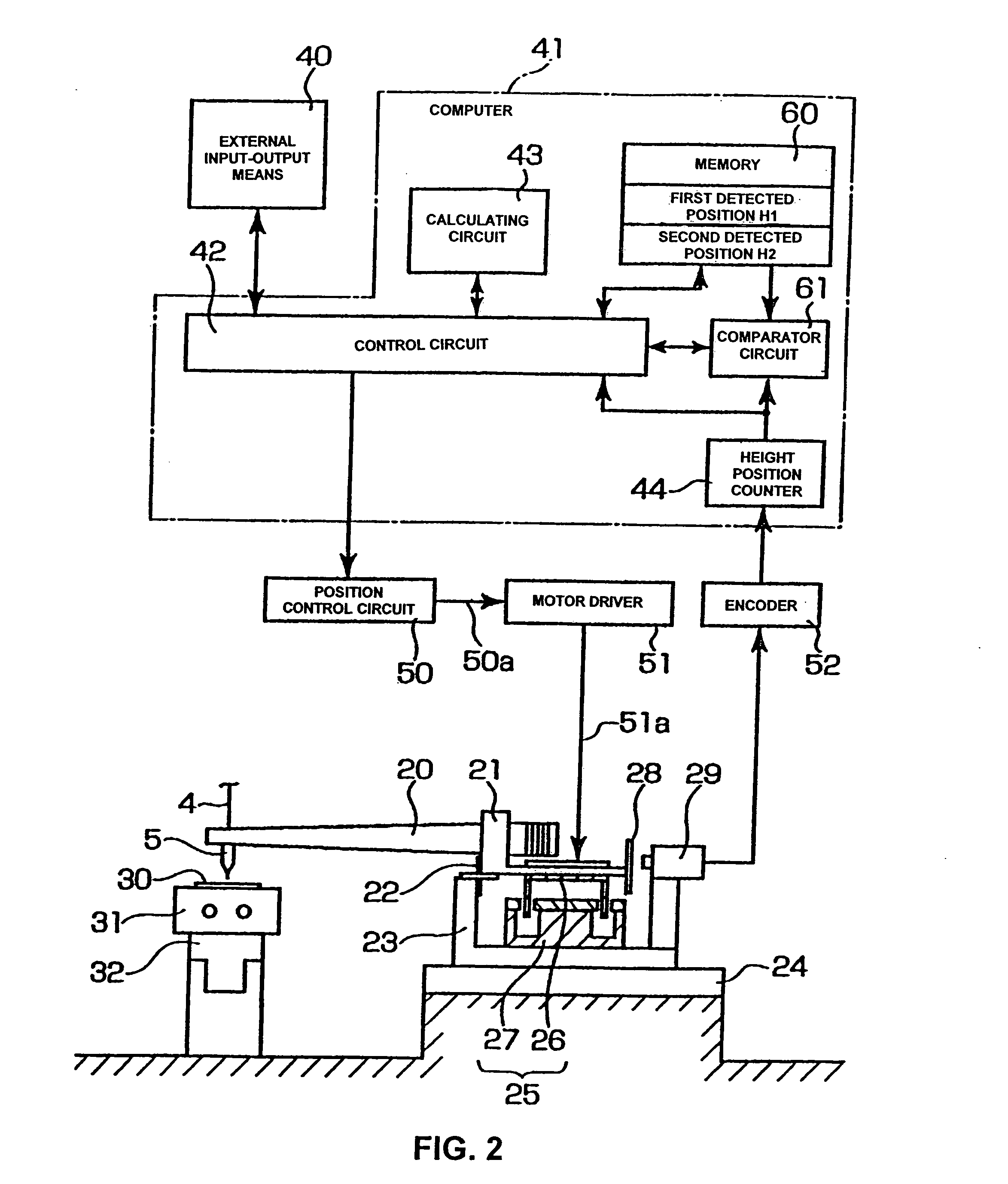
[0031] The first detected position H1 which is shown in FIG. 1(a) and is the level (height) of the lower end of the capillary 5 at the time that secondary bonding of the wire 4 to the bump 10 is performed is stored in the memory 60 of the computer 41 shown in FIG. 2. In other words, the position of the capillary 5 in the state shown in FIG. 1(a) is detected by a position sensor 29, the signal resulting from this detection by the position sensor 29 is converted by a height position counter 44 via an encoder 52, and the value produced by this conversion is st...


PUM

PropertyMeasurementUnit
heightaaaaaaaaaa
structureaaaaaaaaaa
electric poweraaaaaaaaaa

Abstract

A wire bonding apparatus and method involving a computer 41 that has a height position counter 44 that produces height position signals for a capillary 5 by processing signals from a position sensor 29 that detects the position of the bonding arm 20 in the vertical direction. This computer 41 includes a memory 60, which stores the detected position of the capillary 5 at the time that secondary bonding is performed on a bump that is formed in a normal manner on the second conductor, and a comparator circuit 61, which outputs a “bump not-adhered” signal in cases where the output value of the height position counter 44 is outside the permissible error range of the detected position that is stored in the memory 60.

Description

BACKGROUND OF THE INVENTION [0001] 1. Technical Field [0002] The present invention relates to a wire bonding method and apparatus for connecting a wire to a first conductor and a bump on a second conductor after such a bump has been formed on the second conductor. [0003] 2. Description of the Related Art [0004] In wire bonding, since a ball formed on the tip end of the wire is bonded to the first conductor as a primary bonding, the joining properties are good. However, to the second conductor, since the wire without a ball is bonded as a secondary bonding, the joining properties are poor compared to the joining properties of the primary bonding. Accordingly, a unique technique is used, in which a bump is formed on the second conductor, and then the wire is connected between the first conductor and the bump on the second conductor. [0005] Japanese Patent Application Laid-Open (Kokai) Nos. H10-112471 and 2002-280410, for instance, respectively disclose such a wire bonding method as de...

Claims


Application Information

Patent Timeline
Patent Type & Authority Applications(United States)
IPC IPC(8): H01L21/60B23K20/00
CPCB23K20/004H01L24/48H01L2924/01033H01L2924/00014H01L2924/3011H01L2924/01082H01L2924/01006H01L2924/01005H01L2924/01004H01L2224/85986H01L2224/85399H01L2224/85051H01L2224/78901H01L2224/78301H01L2224/4848H01L2224/48479H01L2224/48471H01L2224/48465H01L2224/48091H01L24/78H01L24/85H01L2224/05599H01L2224/85186H01L2224/45099H01L2924/00H01L2924/15787H01L2224/4554B23K20/00H01L21/60
Inventor TAKAHASHI, KOICHI
Owner SHINKAWA CO LTD
Why Eureka
Try Eureka