System and method for producing a detector position map

a detector position and position map technology, applied in the field of imaging devices, can solve the problem that the simple mapping scheme is generally not accura

Inactive Publication Date: 2005-03-24
GENERAL ELECTRIC CO
View PDF10 Cites 18 Cited by
  • Summary
  • Abstract
  • Description
  • Claims
  • Application Information

AI Technical Summary

Problems solved by technology

One of the challenges in designing a high resolution PET scanner relates to the space requirements of the electronics associated with the detector crystals, in particular the photomultiplier tubes (PMTs) which are situated behind the detector crystals.
However, this simple mapping scheme is generally not accurate due to non-linearity in the analog parts of the detector and manufacturing differences between detector crystals.

Method used


Image

  • System and method for producing a detector position map
  • System and method for producing a detector position map
  • System and method for producing a detector position map

Examples


Embodiment Construction

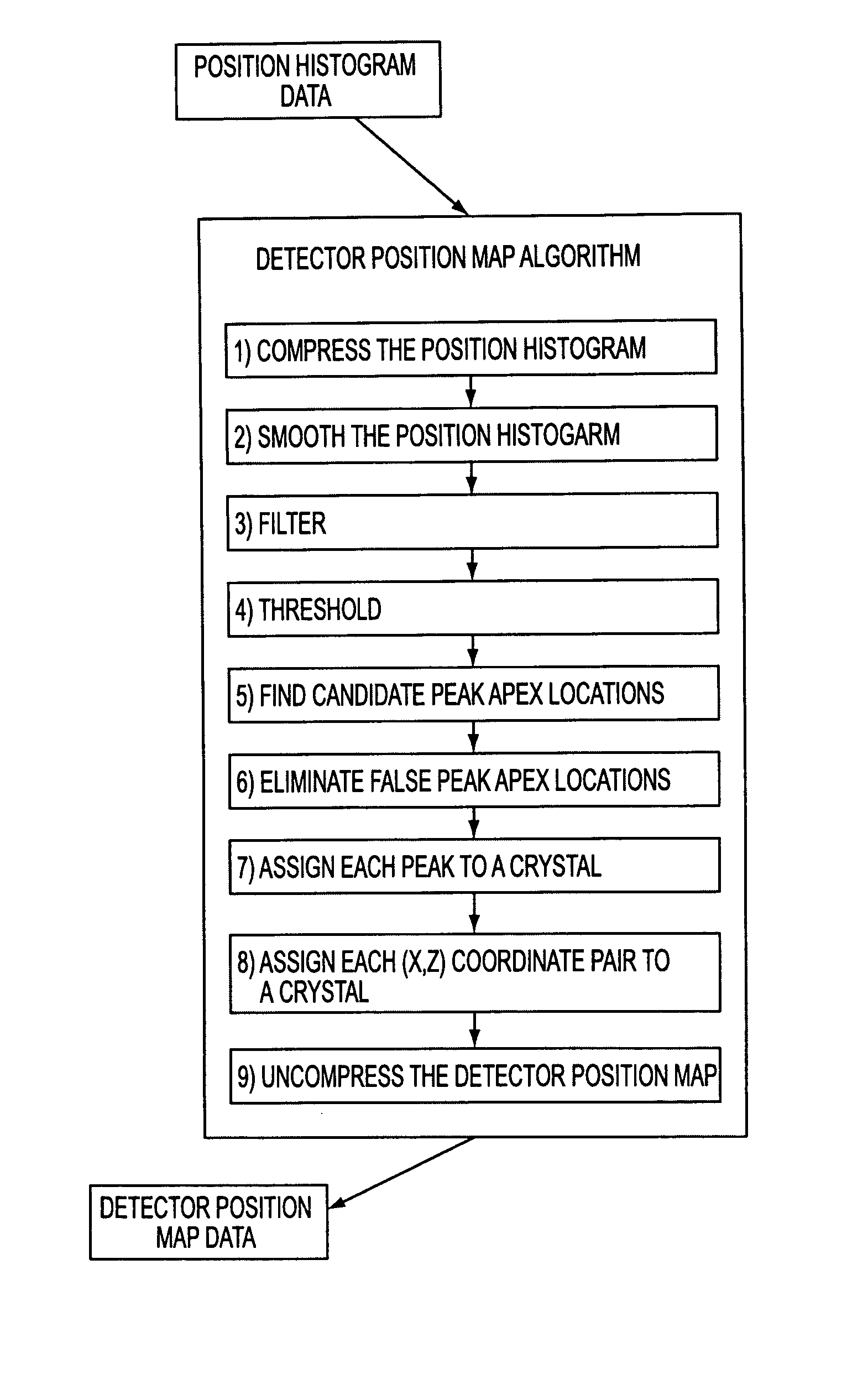
The operation of a PET scanner will be described, followed by a description of the generation of the detector position map used by the scanner to map events to a particular detector in the array.

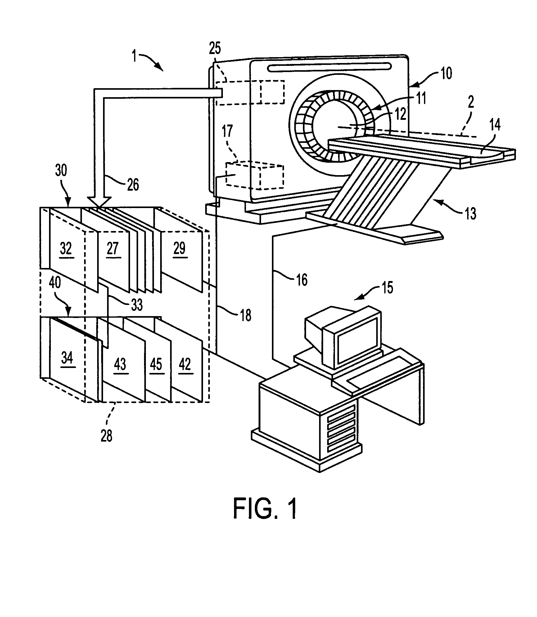
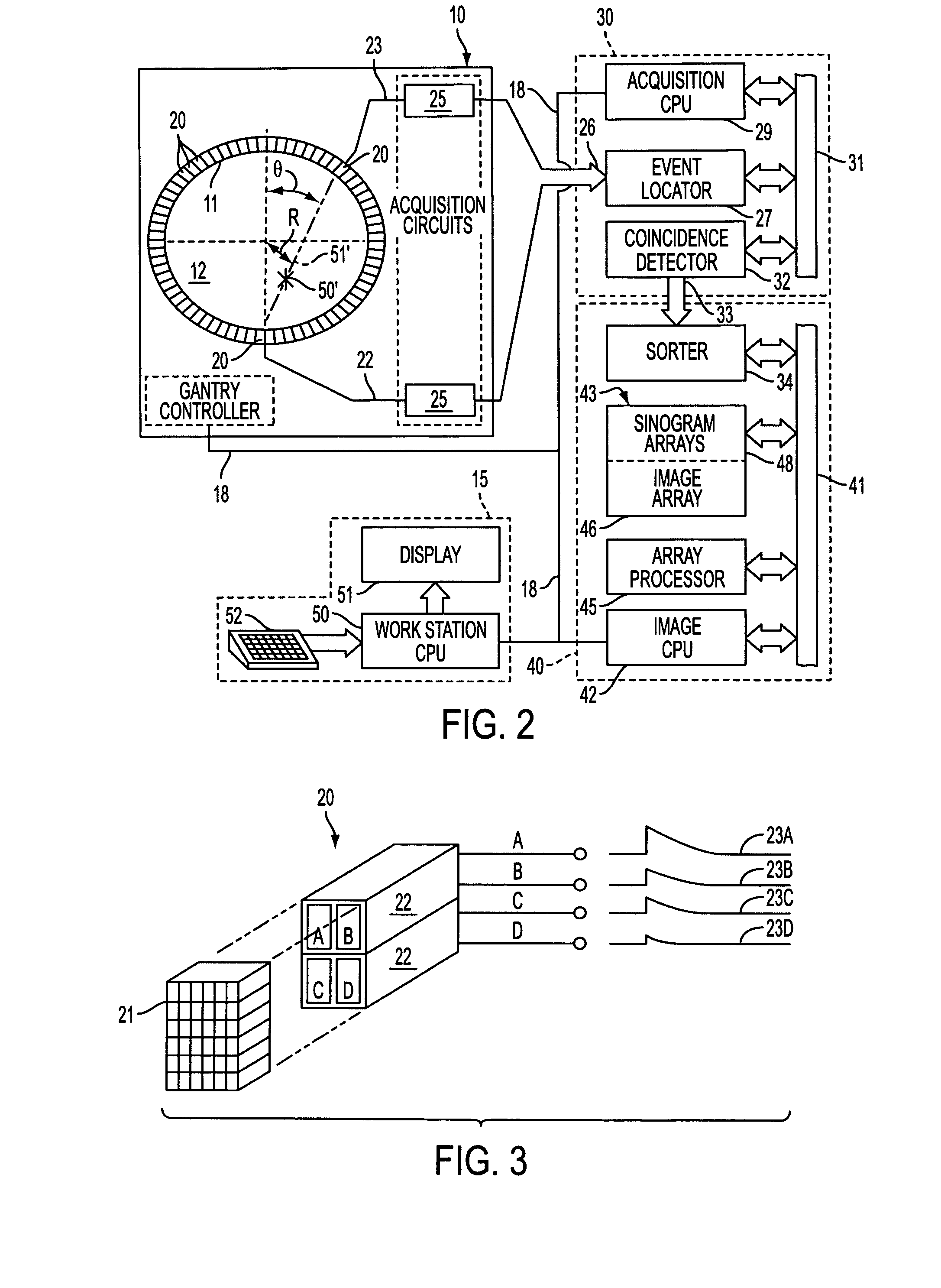
FIG. 1 illustrates an example of a PET scanner 1 which includes a gantry 10 supporting a detector ring assembly 11 about a central opening or bore 12. The detector ring assembly 11 is circular in shape and is made up of multiple detector rings (not shown) that are spaced along a central axis 2 to form a cylindrical detector ring assembly. According to one embodiment, the detector ring assembly 11 includes 24 detector rings spaced along the central axis 2. A patient table 13 is positioned in front of the gantry 10 and is aligned with the central axis 2 of the detector ring assembly 11. A patient table controller (not shown) moves the table bed 14 into the bore 12 in response to commands received from an operator work station 15 through a serial communications link 16. A gantry controller 17...


PUM


Abstract

The invention relates to a system and method for generating a detector position map for an array of detectors. The detector position map comprises a map which converts measured position coordinates from a detection event to the detector in the array which detected the detection event. The method comprises the steps of illuminating an array of detectors with a source of radiation to generate a histogram, the histogram comprising an event count as a function of two dimensions, the two dimensions corresponding to a face of the array of detectors, wherein the histogram comprises a plurality of first peaks; modifying the histogram to comprise a plurality of second peaks, wherein the second peaks have a greater degree of isolation from each other than the first peaks; and for each detector, determining a region on the detector position map which corresponds to the detector, each region being based on a position of one of the second peaks.

Description

BACKGROUND OF THE INVENTION The present invention relates generally to an imaging device, and more particularly to a system and method for mapping a detected radiation event to a particular detector in a medical imaging device such as a positron emission tomography scanner. A positron emission tomography (PET) scanner detects gamma rays which emanate from the patient. In a PET scan, the patient is initially injected with a radiopharmaceutical, which is a radioactive substance such as FDG ([18F] fluorodeoxyglucose) which emits positrons as it decays. Once injected, the radiopharmaceutical becomes involved in certain known bodily processes such as glucose metabolism or protein synthesis, for example. The emitted positrons travel a very short distance before they encounter an electron, at which point an annihilation event occurs whereby the electron and positron are annihilated and converted into two gamma rays. Each of the gamma ray has an energy of 511 keV, and the two gamma rays a...

Claims


Application Information

Patent Timeline
Patent Type & Authority Applications(United States)
IPC IPC(8): G01T1/164
CPCG01T1/1647
Inventor STONGER, KELLY ALANWILLIAMS, JOHN JAY
Owner GENERAL ELECTRIC CO
Why Eureka
Try Eureka