Imaging of biological samples using electronic light detector

a technology of electronic light detector and biological sample, applied in the field of imaging systems and methods, can solve the problems of preventing the broad use of such technologies, requiring training and maintenance, and requiring sophisticated and expensive instruments such as conventional microscopes

Inactive Publication Date: 2006-12-05
RGT UNIV OF MINNESOTA
View PDF75 Cites 168 Cited by
  • Summary
  • Abstract
  • Description
  • Claims
  • Application Information

AI Technical Summary

Benefits of technology

[0015]A system for use in detecting biological material of a biological sample according to the present invention includes a positioning apparatus for providing a biological sample in a sampling position. The biological sample (e.g., a micro-array or a gel) includes biological material associated with a biological material holding structure with the biological material holding structure having first and second opposing sides. The system further includes an electronic light detector array with the electronic light detector array including a plurality of detector pixels located at particular detector pixel addresses. The plurality of detector pixels face the first side of the biological sample to receive light therefrom. A light source is operable to provi...

Problems solved by technology

These conventional microscopes are sophisticated and expensive instruments that require training and maintenance.
A single microscope objective typically has multiple lenses that are generally very expensive.
One of the challenges in microscopy is making the microsc...

Method used


Image

  • Imaging of biological samples using electronic light detector
  • Imaging of biological samples using electronic light detector
  • Imaging of biological samples using electronic light detector

Examples


Embodiment Construction

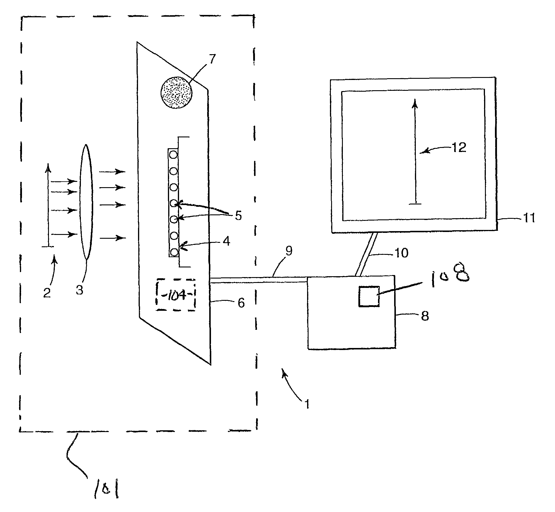
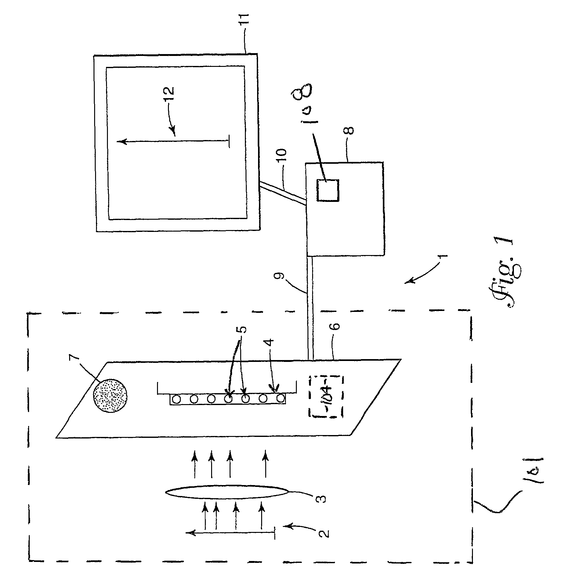
[0046]The present invention provides inexpensive devices and methods for resolving light (e.g., emitted light by fluorescent labeled nucleic acid spots) representative of biological samples (e.g., nucleic acid spots on a micro-array such as a DNA chip, protein bands of a 1-D or 2-D gel, etc.) for the detection thereof. As used herein, biological samples refers to biological material (proteins, nucleic acids, tissues, etc.) associated with a biological material holding structure (e.g., a micro-array substrate such as a DNA chip substrate, a gel, etc.) in a manner that allows for detection of the biological material, or portions thereof (e.g., with the use of markers such as dyes, tags, labels, or stains), such as through the use of imaging (e.g., direct mapping).

[0047]The term, “biological samples” refers not only to the biological material itself (proteins, nucleic acids, tissues, etc.) but also to other materials associated therewith used for detection of the biological material, o...


PUM

PropertyMeasurementUnit
Lengthaaaaaaaaaa
Lengthaaaaaaaaaa
Lengthaaaaaaaaaa

Abstract

A system and method using an electronic light detector array, e.g., a CCD or a CMOS-based detector array, is used to acquire a visual image of a biological sample that includes biological material associated with a biological material holding structure (e.g., a DNA spot array on a DNA chip, protein bands in a 2-D gel, etc.). For example, fluorescence from a biological sample may be detected.

Description

CROSS-REFERENCE TO RELATED APPLICATION(S)[0001]This application is a continuation-in-part of U.S. patent application Ser. No. 09 / 434,027, filed on Nov. 4, 1999 now U.S. Pat. No. 6,784,982, which is incorporated herein by reference.FIELD OF THE INVENTION[0002]The present invention pertains to imaging systems and methods. More particularly, the present invention relates to imaging and / or mapping of biological samples using electronic light detectors.BACKGROUND OF THE INVENTION[0003]Various conventional approaches have been used to visualize the surface of a biological sample, e.g., DNA spots of a micro-array such as a DNA chip, protein bands in a one dimensional (1-D) or two dimensional (2-D) gel, etc. For example, a DNA chip is generally a rigid flat surface, typically glass or silicon, that may have short chains of related nucleic acids spotted, e.g., DNA spots, in rows and columns, i.e., an array, thereon. Hybridization between a fluorescently-labeled DNA and specific locations on ...

Claims


Application Information

Patent Timeline
IPC IPC(8): G01N21/03C12N15/09G01N33/53C12Q1/68G01N21/00G01N21/64G01N37/00G06K9/74G06T1/00H01L27/14H01L31/09H01S3/00
CPCG06T1/0007B01J2219/00529B01J2219/00702
Inventor BLUMENFELD, MARTINSANDERS, MARK A.TALGHADER, JOSEPH J.GRENZ, JESSE R.
Owner RGT UNIV OF MINNESOTA
Why Eureka
Try Eureka